Hi again, Folks;
Thanks to diyAudio members, I have been able to repair a few of my broken toys.
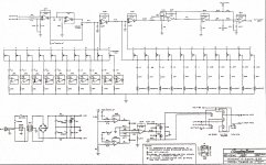
Next in line; a soundcraftsmen tg-3044-r equalizer, 1/3 octave stereo, channel B not functioning. I was never thrilled with this product, and things aren't getting any better! I will attach the schematic from (Electrotanya).
This is proving more of a challenge than it's worth (at least with my amatuer talent) , the components are not numbered on the schematic or on the pcb.
IC's are also not numbered, so it is tricky determining which op-amps are in which IC. I see that Soundcraftsmen got their just deserts!
The pcb quite opaque, and so following circuit paths....anyway, I am hoping someone might have some guidance or a better schematic, thanks,
Peter
Thanks to diyAudio members, I have been able to repair a few of my broken toys.
Next in line; a soundcraftsmen tg-3044-r equalizer, 1/3 octave stereo, channel B not functioning. I was never thrilled with this product, and things aren't getting any better! I will attach the schematic from (Electrotanya).
This is proving more of a challenge than it's worth (at least with my amatuer talent) , the components are not numbered on the schematic or on the pcb.
IC's are also not numbered, so it is tricky determining which op-amps are in which IC. I see that Soundcraftsmen got their just deserts!
The pcb quite opaque, and so following circuit paths....anyway, I am hoping someone might have some guidance or a better schematic, thanks,
Peter
Wow, real inductors in the HF section! How's the hum? I'd imagine the high frequency distortion isn't good when any boost or cut is made to the treble...
I'd junk it if I were you. It's very crude to say the least 😉 .
I'd junk it if I were you. It's very crude to say the least 😉 .
Thanks monty;
I was just hoping this would be a learning experience. I have spent way to much time on something that could be replaced for $100. Maybe that is the lesson, still it will be sitting in the garage when not in use, (it is for my backyard system) so it would have been nice to save it.
I will probably take your advice; at least it is a nice rack mount box for a future project, and a lifetime supply of slider pots!
Thanks, Peter
Oh well. If you can understand how it works, then you haven't wasted any time!
Save the box for a future project. The power transformer will also be good for a preamp or other small signal audio project.
Save the box for a future project. The power transformer will also be good for a preamp or other small signal audio project.
Another thing I noticed was electrolytic capacitors being used to set the frequency of some of the lower bass controls. This is a real no-no. They have a very wide tolerance so accuracy will be poor and the capacitance decreases as they age which will result in the frequency rising. Very shoddy 😀 .
Well, if they were smart they used a low-leakage series at least. I can't imagine an engineer in the late '70s wouldn't have known that standard electrolytics aren't exactly precision devices.
What type (or types) of opamps is being used anyway? From the circuit I'd be guessing maybe parts TL08x/TL07x, parts 4558 of one kind or another (or maybe LF356)?
What type (or types) of opamps is being used anyway? From the circuit I'd be guessing maybe parts TL08x/TL07x, parts 4558 of one kind or another (or maybe LF356)?
Hmm... I wouldn't imagine they would have to be low leakage, but the distortion performance would have been significantly compromised as inherently a very large part of the signal voltage would be across those caps. Electrolytics tend to produce horrible distortion, even when briefly reverse biased. We get around this by making them very high value so there is no real voltage drop across them in the audio range, but in this case they are being used as time constants without any positive bias. Nasty 😕 .
So the bass controls are severely compromised by the electrolytic capacitors and the treble controls are also heavily compromised by the nonlinear distortion caused by the saturation of the iron cores in the inductors...
I should hope that the op-amps are bipolar so that a small bias can develop across those electrolytic capacitors (although which ones, I'm not so sure as they don't have any input or output decoupling caps, great job there, lads 😉 ), but having seen what I have so far in this design I don't really know what to expect! 😀
Hi Folks;
Just an update; It's working!.. I was losing the signal at the op-amp just after the sub-sonic filter switch. I removed that IC and replaced it with an IC from the other channel. (All the IC's are the same). After the swap, both channels are functioning. It is my guess that there was a bad connection in that IC socket.
I am very disappointed in the quality of this unit, and thanks everyone for informing me of things to avoid in the future. I think I will steer clear of an used Soundcraftsmen products. Never the less, I am happy to have the unit working. It is in a dusty humid environment and would not have wanted to replace it with better unit.
Thanks everyone for your input, Peter in Canada
I have the very same model and need a replacement master fader because it was smashed in, from what I can make out it is a 50k slider and has a trvel of about 48mm, it is also very narrow about 8mm can anyone point me in the right direction to find a replacement?
- Status
- Not open for further replies.
- Home
- Source & Line
- Analog Line Level
- Soundcraftsmen TG-3044-r equalizer, Ready for the scrap heap?