hello, i realize this is a old post but i will ask anyways. i need to adjust my bias on a pm860 ..the amp is similar to the pcr800 ..would you know by looking at the board the resistors i need to go across to check bias ...any help would be greatly appreciated.Hello,
I have one of these now on my bench for repair. They have a unique power supply stage with SCR's in place of bridge diodes. The SCR's are supposed to behave like in a halogen light dimmer, stabilizing the voltage. Unfortunately, instead of +-70V, I get +-84V which is wrong, it seems, as the main caps are rated for 75V DC. The amp is also buzzing rather loudly (low-frequency spikes) on both channels. On the other hand, offset is perfect both L and R, so it seems the power mosfets and the preceding transistors are ok.
Can anyone please explain to me how this kind of regulation works, and what to check as it seems all four SCR's are full on, even in idle ?
Thank you in advance
Marco
Attachments
There is not much headroom in this amp. The regulation is meant to remove the variable part of the transformer voltage sag that occurs under load. And since this is a MOSFET amp, it needs up to 12V to fully turn them on. 70V-12V=58V, 58V x .707=41V RMS, 41^2/8 ohm= 210 watts into 8 ohm. Just above the 205W rating. Their class H amps do the same thing by setting the lower rail voltage to the RMS of the transformer. That way the variable portion of the voltage is stored in the high voltage rail and is added to the low voltage output rail when needed. They have a higher overhead with that design, but the point is to provide constant voltage for the output transistors to draw from, compared to traditional open regulation which has headroom and clipping that ramp up and down with the power supply cycles.From the description:№2
What is so special about this amplifier is the PCR part, which is an acronym for Phase Control Regulation. To understand this term better, it means the power supply is Regulated. And this regulation is made possible by controlling the phase angle of the thyristors feeding the filter capacitors, hence the term Phase Control Regulation.
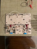
The transformer secondaries are connected at the left. They are at 68-0-68Vac. After rectification, the output is at +/- 70Vdc. This voltage is regulated, meaning it doesn’t sag under load. I can verify this because when I bench tested this PCR800 at full power into an 8Ω dummy load, the supply rail voltages stayed at +/- 70Vdc.
The red box at the top is the phase control section. This is the heart of the PCR. This circuit controls the firing of the thyristors. Since the voltage is regulated at +/- 70V, it indicates that the thyristors are fired before 90°. There is a +/- 25V headroom in the power supply because in a conventional, non-regulated linear supply, the output will be at +/- 95V.
The circuit enclosed in blue is for temperature sensing.
Actually, transformer sag may be an inaccurate description of what's happening. There is bit of that going on, but what I meant was power supply voltage sag. This being the transition of the power caps storing peak transformer voltage at no load, to transformer RMS voltage at full rated transformer load. What's interesting about these 205W per channel PCR amps is that they use a 500VA transformer. That is usually good for 75W per channel in many vintage receivers designed for the standard temperature rise for a 500VA transformer. These PCR amps get away with over-driving them by having them fan cooled and temp/current protected, as well as the fact that music hitting the clipping levels doesn't actually use that much average power.
Actually, transformer sag may be an inaccurate description of what's happening. There is bit of that going on, but what I meant was power supply voltage sag. This being the transition of the power caps storing peak transformer voltage at no load, to transformer RMS voltage at full rated transformer load. What's interesting about these 205W per channel PCR amps is that they use a 500VA transformer. That is usually good for 75W per channel in many vintage receivers designed for the standard temperature rise for a 500VA transformer. These PCR amps get away with over-driving them by having them fan cooled and temp/current protected, as well as the fact that music hitting the clipping levels doesn't actually use that much average power.
I was almost going to give up on this amp,thanks so much! Should i replace all the j50/j135 outputs ,or can i just search for one. I used a peak atlas dca55 to test and there is only 1 j50 with bad part reading. I also dont know what the 2 transistors are in the middle under the heatsinks. the part # looks like pn2907 ?
You can replace one if that's all you want to do. Otherwise the only option is Exicon 10P20 and 10N20 transistors from Profusion. Those 2n2907 are for temperature sensing, they rarely go bad. You can check the junctions. And the temp sensing voltages are checked at the op-amp after it's running.
Yeah, I dont know if i want to replace all the mosfets .My concern is matching of course. I was trying to adjust the bias when i touched something that caused the output to go bad. I suspected that it was those 2 resistors to adjust bias but i was not sure.... the 400mv is that with the fan in place? i was thinking a 100mv per output device since this has a total of 6 Mosfets per channel ...i also had a audible hum through my speakers with nothing connected to the inputs. ....turned out to be 1 of the input jacks since i converted from Phono plugs. ...I have 2 of these amps 1 is up and running.......thanks for your help Frank.
Actually you can only check one junction of the 2n2907's because they are shorted from base to collector on the board. They are just there for the junction voltage. The voltage drops as they heat up and that voltage is compared to the temp setting voltage to determine fan operation and PCR limiting.
It doesn't matter if the fan is in place, I usually have it out of the way. The .4V on that resistor is the difference in voltage between the output transistor gates from positive to negative devices. The more voltage; the more current the transistors idle at. Amperage could be roughly calculated by measuring across the current sensing resistor and multiplying the amperage x3, but I don't feel the need to do that other than in special diagnostic cases. I set bias to the factory .4V and watch the power usage on a watt meter that the amp is plugged in to. 20-25W is the typical range for these amps to run without the fan hooked up. The fan adds another 20W on low speed idle. If something is wrong with the idle power, I notice it right away and start looking.Yeah, I dont know if i want to replace all the mosfets .My concern is matching of course. I was trying to adjust the bias when i touched something that caused the output to go bad. I suspected that it was those 2 resistors to adjust bias but i was not sure.... the 400mv is that with the fan in place? i was thinking a 100mv per output device since this has a total of 6 Mosfets per channel ...i also had a audible hum through my speakers with nothing connected to the inputs. ....turned out to be 1 of the input jacks since i converted from Phono plugs. ...I have 2 of these amps 1 is up and running.......thanks for your help Frank.
I also start these on a dim-bulb-tester to make sure all is good before going any further. I just us a 65W bulb with an alligator jumper cut in half and soldered to it with some large heat shrink tube to cover the bulb contacts (electrical tape works too). I jump it across the switch, could remove the fuse and jump there too. It's cheap and versatile, and stores in the box the bulb came in.

So looking at the schematic, +/- 70V feedback through R11 and R19 to U2C, U2D, which throttle U2B, the saw tooth pulse phase comparator, the output of which drives Q3,Q4 and then Q5,Q6 to the SCRs. If any of these transistors is shorted, you will get the SRCs firing immediately and full output to the caps. I can easy see Q5 or Q6 failing.
The SCRs are supposed to fire after the sine wave peak, after 90 & 270 degrees where the AC voltage is falling. This creates a nasty current spike, but so does a normal diode to cap input power supply. It's not much different except the current spike is later in the AC cycle. This will fail with a square wave power inverter.
You want to check the sawtooth wave at C1 R5 and the DC feedback on C2, but first I would check Q3-6. And the voltage adjustment pot R8 and 6V Zener reference voltage. With more than 70V, CR13,CR14 should be near +15V in an effort to raise the voltage on C2 so that the SCRs fire later.
Good luck.
Last edited:
There is not a phase angle that it is "supposed" to fire at. They are meant to fire the SCRs when ever the voltage falls below regulated voltage, whether that is immediately after the zero crossing, 90 degrees or in the last 10, it doesn't care. Also, I think we've moved past the original OP's question on regulation and on to @crooner2264 shorted output and bias adjustment, although the OP - @Orit has not posted any more progress on the amp...
- Home
- Amplifiers
- Solid State
- Soundcraftsmen PCR800 Power Amp Supply