I would take any such claim by an Audio cable manufacturer with a pinch of salt, its marketing rubbish to make them sound good.
Indeed. 'Nordost secured the rights to use it for audio.'.What a load of bull.
Jan
Yep, they could have bought the cable from any electrical supplier probably🙂
Just reading some stuff on their site, it is priceless, love high end cable sites....
On military vehicle comms, they don't use silver cable these days, just boring copper....
Just reading some stuff on their site, it is priceless, love high end cable sites....
On military vehicle comms, they don't use silver cable these days, just boring copper....
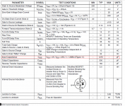
No, he was absolutely correct with 1.5 nF input capacitance.Are you talking about the output devices? If so, your capacitance is off by an order of magnitude- Crss is usually 50-70pF for power devices.
Attachments
Last edited:
One guy paid big money to have some mercury cables made in PVC tubes. I doesn't need the obvious to be said. I asked the other obvious question. How did it sound ? " Absolutely awful ".
Remember this tone arm, with mercury contacts in the arm base to avoid torque from the wiring?
Keith Monks Laboratory Manual - Classic Uni-Pivot Tonearm - Vinyl Engine
No, he was absolutely correct with 1.5 nF input capacitance.
Crss is the important parameter for the output device, at least if the output stage is the usual comp source follower.
Have you ever measured a nonlinear input capacitance of the MOSFET push-pull output stage with something like IRF240/9240??
Indeed. 'Nordost secured the rights to use it for audio.'.What a load of bull.
Jan
Did Nordost or Bybee use this line first? Amazing that these folks say these things and maintain any credibility.
The similarity grows...
"When cables are manufactured they do not have any directionality. However, as they break in, they acquire directionality.
Although the cable signal is an alternating current, small impurities in the conductor act as diodes allowing signal flow to be better in one direction over time. This effect is also called quantum tunneling, which has been observed in experiments over 25 years ago. Regardless of the purity of the metal used, there are still diode effects in all conductors. In addition, the insulation material will change when it is subjected to an electrical field."
So you can't get the direction right off the spool, like everyone else says? What a tangled web we weave.
Last edited:
Have you ever measured a nonlinear input capacitance of the MOSFET push-pull output stage with something like IRF240/9240??
There are several contributors to this, the argument would be better with a picture or two to illustrate. A source follower to the first order bootstraps the input capacitance but in reality there is a dynamic voltage across Cgs needed to make current. This will make displacement current as well as Vin across Crss both need to be provided by the previous stage. Now consider the phase of the load for more complication.
Crss is a strong function of VDS with the worst case at lowest VDS. If you want to swing to say 3V of the supply rails then 1.5nF is absolutely spot on for an IRF240/IRFP240 pair. Ooops, sorry brain fart - the pairing is IRF240/IRF9240 and the P-channel device has lower capacitance. Call it 1.2nF.
Last edited:
Have you ever measured a nonlinear input capacitance of the MOSFET push-pull output stage with something like IRF240/9240??
Yes, but not with those specific devices. Input capacitance was just what you'd expect from the ratings- there is some nonlinearity, but it's manifest more near the clipping point (again, exactly what you'd expect from the Crss vs Vds curves).
http://www.st.com/web/en/resource/technical/document/datasheet/CD00002071.pdf
See figure 8.
edit: I looked at similar curves for the 15+ year old devices you mentioned. Crss is indeed worse than in modern devices.
Sorry, it is not about Crss only. Have you read it in some textbook?
Follower with IRF240 has input capacitance about 800pF, Crss is only 81pF.
Follower with IRF240 has input capacitance about 800pF, Crss is only 81pF.
Sorry, it is not about Crss only. Have you read it in some textbook?
Yes, and built some myself. Of course, I did a better job of choosing appropriate (more modern) devices than the examples you gave.
Sorry, it is not about Crss only. Have you read it in some textbook?
Follower with IRF240 has input capacitance about 800pF, Crss is only 81pF.
Guys a picture what you are discussing would help. PMA a source follower loaded (for instance in the limit) by a current source does not have any contribution from Ciss at the input. Only a portion of Ciss, related to the ratio of gm to the load conductance, causes a displacement current load on the previous stage. At about a gain of .9 for the source follower the Ciss and Crss contribution is comparable (in your case) but in a normal circuit the Ciss is at a lower bias voltage and at a more non-linear point.
Measuring the capacitance of gate to source and drain virtually grounded, does not apply in situ for an amplifier source follower output stage.
Last edited:
SY, you are quibbling. PMA is a real analog designer, and he, as well as I, know that the IRF240 is the more practical and reasonable device to use, UNLESS you were making a Class D amp. WHERE is the safe area graph, SY?
As far as Scott is concerned: A follower does negate SOME of the input capacitance, but only a fraction, depending on loading conditions, Gm, etc.
You have to have a 'perfect' transfer from output to input to totally negate the input G-S capacitance, and this is virtually impossible.
You have to have a 'perfect' transfer from output to input to totally negate the input G-S capacitance, and this is virtually impossible.
WHERE is the safe area graph, SY?
For which device? For the 24NF10, it's Figure 1 on the datasheet.
As far as Scott is concerned: A follower does negate SOME of the input capacitance, but only a fraction, depending on loading conditions, Gm, etc.
You have to have a 'perfect' transfer from output to input to totally negate the input G-S capacitance, and this is virtually impossible.
I stated my conditions exactly no need to repeat them. You can, and I have, built a fully bootstrapped follower with 100's of femto-farads of input capacitance. In fact with a little care you can null it almost identically to zero. The circuit was in Jan's magazine but I doubt you read anything outside the posse.
I've had my own views on slewing and John and I choose to agree but not over the detail.
...
And I think it's both.
I agreed with John on 100 V/uS was a good number. More only if the amp is really very high power.
But I also feel we should let the voltage part of the rip at higher than teeny seeny currents they are sometimes ran at. I believe a decent VAS should be biased at 15-20 mA.
- Status
- Not open for further replies.
- Home
- Member Areas
- The Lounge
- Sound Quality Vs. Measurements