Please list some that are happy at 60 V if people know.
If you're not interested in hearing about museum types, try Linear Systems 800 series.
http://docs-europe.electrocomponents.com/webdocs/0468/0900766b804683c1.pdf
This is where I might have to start and use +/- 35 V rails .
Then cascode for higher voltages. Ron about 40R at 0 amps. Looks to have ideal degeneration.
This is where I might have to start and use +/- 35 V rails .
Then cascode for higher voltages. Ron about 40R at 0 amps. Looks to have ideal degeneration.
the historical perspective on testing -
Over here in DIY-land we hear only of DBT... but there are other 'scientific' tests as well which are no more or less valid. The tests have to be carefully developed to include perceptual knowledge. And perceptual knowledge is always expanding, making some tests to be scrapped for a 'better' test. The AES and other literature is full of history of tests which get done over with more refined results. It wasnt THAT far back that scientific tests showed much fewer bits and sampling rates to be undetectable..... It was the meta-data evidence that drove the technology to be better and then new tests had to be done and finding the bits and rates need to be higher before they are not significant.
One example is in testing CODECs. Take a run down of the different scientific tests and results at this point in time; "Codec Listening Test at wikipedia.org. Then go find the background for those tests to see how they evolved.
This will high-lite the point(s) I have made earlier.
THx-RNMarsh
Last edited:
Nigel, you have to take notice of a few things about jfets:
First, they can get VERY leaky with high voltage on them, that is close to the voltage spec limit of the particular device chosen.
Second, they don't dissipate much power across them, because they are invariably in TO-92 packages or something equivalent in power dissipation.
Three, putting random Idss jfets together as a pair will not really work well, even with a servo, so be prepared to match them AT LEAST for Idss which is really easy by the way.
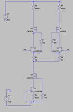
John is right about the Jfets. Here is what I have been doing for some time. The depletion mode mosfets are good for 350V and used this way will reduce the input capacitance and cap modulation a lot. 150V supply should be enough for any amplifier driving dynamic drivers except perhaps motors. The parts are not real cheap but not expensive for what they do. Mouser stocks the Supertex parts. The TO92 is around $.60 in singles. You could use the jfets to referenced. There was no noise spec but the Rds on suggests they may be low noise. Use a trimmer for the two 10 Ohm resistors to dial out the offset.
Attachments
Vorbis for better sound quality -
BTW --- Vorbis is one of the better codecs and is free.... careful listeners may want to try/us it.
More info at wikipedia Vorbis.
-THx-RNMarsh
Over here in DIY-land we hear only of DBT... but there are other 'scientific' tests as well which are no more or less valid. The tests have to be carefully developed to include perceptual knowledge. And perceptual knowledge is always expanding, making some tests to be scrapped for a 'better' test. The AES and other literature is full of history of tests which get done over with more refined results. It wasnt THAT far back that scientific tests showed much fewer bits and sampling rates to be undetectable..... It was the meta-data evidence that drove the technology to be better and then new tests had to be done and finding the bits and rates need to be higher before they are not significant.
One example is in testing CODECs. Take a run down of the different scientific tests and results at this point in time; "Codec Listening Test at wikipedia.org. Then go find the background for those tests to see how they evolved.
This will high-lite the point(s) I have made earlier.
THx-RNMarsh
BTW --- Vorbis is one of the better codecs and is free.... careful listeners may want to try/us it.
More info at wikipedia Vorbis.
-THx-RNMarsh
Hello Nigel,On another thread I am trying to design the ultimate low cost 1920's style amp. I have with very little regard as to practicality looked at EF184 TV pentode driving Russian 6A7S double power triode (a bargain and indirectly heated at 6.3VAC). The interesting thing is this seems not to have occurred to anyone. It's 2A3 and 6SN7 and forget it. The valve world is very tight thinking ...
This probably belongs to the other thread, but.. Japanese were building 6AS7G P-P amps as far back as late '80s. I have a book from1989 with schematics, measurements and even chassis layout for such amp. 6080 also has been used in similar manner over there. Then there was a gentlemen in Germany who bought a huge stash of 6AS7G's from me and used them in his SE amps in the early '90s (H.Lepiorz).. I've seen EF184 being used by Japanese hobbyists as well (MJ mag).
Best,
10 Ohm degeneration resistors in your schematic looks a bit too low, Demian. I sort of expected to see something more like 33-47 Ohms.
Or do you see them as merely improving the transistor matching?
Or do you see them as merely improving the transistor matching?
Its for offset trim. Actually I use a 10 Ohm 20 turn pot with 5 ohms from each end to the wiper. Any larger and you start compromising noise performance. You can calculate how much voltage you need from the worst case offset between the fets. If the fets are too far apart in matching (Idss) then they won't cancel distortion properly either but if they are close enough it should work well. In the sim I got 20 dB of gain flat to almost 1 MHz. It has a corner of about 4 KHz with 1 Meg in series with the input, or around 50 pF equivalent capacitance. Those seem similar to the actual circuits I have built.
Nigel, you have to take notice of a few things about jfets:
First, they can get VERY leaky with high voltage on them, that is close to the voltage spec limit of the particular device chosen.
Second, they don't dissipate much power across them, because they are invariably in TO-92 packages or something equivalent in power dissipation.
Three, putting random Idss jfets together as a pair will not really work well, even with a servo, so be prepared to match them AT LEAST for Idss which is really easy by the way.
Thanks John. Good to be told in the best practical way . I am so lazy and always hope for miracles. I get them sometimes.
By a very hard route of deciding DVV I think your cascode is the best. It ticks all the boxes. I take the RF problems to be important. My amp is bipolar and I uses 2K2 series input, 33K and 47pF input RF avoidance.
I have debated to use lets say ECC83 valve as input. Same problems except voltage is OK. For no romantic reason it has some virtue. Gain would be about 50 at a guess? I dare say it has a very small chance. Capacitor coupled output for safety. A friend begged me to look at a hybrid and I did do a bit of work on it.
Hello Nigel,
This probably belongs to the other thread, but.. Japanese were building 6AS7G P-P amps as far back as late '80s. I have a book from1989 with schematics, measurements and even chassis layout for such amp. 6080 also has been used in similar manner over there. Then there was a gentlemen in Germany who bought a huge stash of 6AS7G's from me and used them in his SE amps in the early '90s (H.Lepiorz).. I've seen EF184 being used by Japanese hobbyists as well (MJ mag).
Best,
I like valves to be discussed as this is Subjective verses Measurements. I have to say most carefully designed tube-valve amps have more micro detail in the modern speak.
Funny thing is I am a moderately good transistor amp designer who insists on using a Quad 33/303( keeps me honest). My valve designs are weird caprices I do to say what if ? These have been more accepted as having some excellence. I conclude good transistor amps are the usual and good valve amps for valve religion reasons not. I have a simple advantage. I like my 33/303 and a valve has to be better to even bother spending money on it.
I found out something recently. I have built some speakers that are nearer to something I understand to be ideal. I call it the Caruso effect. That is 500 Hz to 4 kHz should be free of phase shift. By pure accident they are a nice load. No amplifier sounds greatly different through them, even the Audiolab that mostly I detest. Nearly all amps sound far more open through them. By pure accident I have found a truth and have no idea what? The overall sound is very fast. In OB form they were world beaters. In box form distressingly average, good enough for Colleen to love them. Colleen asked what planet I was from when she saw the OB version. I would say in box form 20% as good which is still very very good. The main problem is in boxes they sound like beacons. I guess that is the box sound and why complain. My 20% won't be like yours. It's getting silver when wanting platinum. In many ways silver is better.
Picking up on what John said I think RF filtering is important if rejecting JFET's. My favourite bipolar transistors are 2SA920 or 2SA1085 for input pair . At present I use 2K2 into the input with 33K and 47pF to ground. Could I do better with a small air-cored inductor in addition to 2K2? Douglas Self says these input resistors are a NoNo. I think not? Rather upsetting to say J FET not the answer. Looking at op amps it seemed a walk in the park. Not if I have to make them cascodes. Far better to make a very low noise bipolar happier at VHF.
I have always assumed an ideal re for the long tail pair to be 50R per device ( 500 uA each) . If I need more current I use external resistors. Is this too simplistic to say 50R about right? The point being there will be a noise trade off and that is not to be ignored.
Could it be the input pair the most crucial part of the amp?
I can't seem to find any good discussion about (lateral) MOSFET output combined with BJT driver stage vs the opposite solution for class AB amplifiers. Which one measures / sounds better?
Can someone share a link or personal opinion on the subject?
Thanks.
Vlad
Can someone share a link or personal opinion on the subject?
Thanks.
Vlad
Picking up on what John said I think RF filtering is important if rejecting JFET's. My favourite bipolar transistors are 2SA920 or 2SA1085 for input pair . At present I use 2K2 into the input with 33K and 47pF to ground. Could I do better with a small air-cored inductor in addition to 2K2? Douglas Self says these input resistors are a NoNo. I think not? Rather upsetting to say J FET not the answer. Looking at op amps it seemed a walk in the park. Not if I have to make them cascodes. Far better to make a very low noise bipolar happier at VHF.
I have always assumed an ideal re for the long tail pair to be 50R per device ( 500 uA each) . If I need more current I use external resistors. Is this too simplistic to say 50R about right? The point being there will be a noise trade off and that is not to be ignored.
Could it be the input pair the most crucial part of the amp?
My favorite BJTs for the input are 2SC2240/2SA970.
Regarding the input filter, Nige I think you would do better to consider my favorite option, which is 2K2 with 270 pF to the ground, cutoff frequency a nick above 200 kHz.
So long as your amp is able to internally (i.e. without that filter) do something like 400 or 500 kHz, after which you limit that to 200 kHz, since it's a first order filter, its phase shift is small and high, therefore the effect at 20 kHz is minimal, and it completely knocks out even the AM band. Obviously, your chances of ever having any TIM are also greatly reduced, as the amp will always be faster than the fastest signal at the input.
Remembereing and supporting what Demian said about input FETs, if biased at 4.5-5 mA per device, they can be really linear to 800 kHz and above, so they too are saved any emeberassment of oscillating with some rogue signal at a very high frequency.
Its for offset trim. Actually I use a 10 Ohm 20 turn pot with 5 ohms from each end to the wiper. Any larger and you start compromising noise performance. You can calculate how much voltage you need from the worst case offset between the fets. If the fets are too far apart in matching (Idss) then they won't cancel distortion properly either but if they are close enough it should work well. In the sim I got 20 dB of gain flat to almost 1 MHz. It has a corner of about 4 KHz with 1 Meg in series with the input, or around 50 pF equivalent capacitance. Those seem similar to the actual circuits I have built.
Got it, thank you, Demian.
With you around, I shall in no time become a FET fedayeen (religious believer).😀
I can't seem to find any good discussion about (lateral) MOSFET output combined with BJT driver stage vs the opposite solution for class AB amplifiers. Which one measures / sounds better?
Can someone share a link or personal opinion on the subject?
Thanks.
Vlad
Hi Vlad, nice to see you here. 🙂
Please someone, help this nice fellow with his above question. I know some of you guys (several actually) can help him out, so please don't be shy.
I can't seem to find any good discussion about (lateral) MOSFET output combined with BJT driver stage vs the opposite solution for class AB amplifiers. Which one measures / sounds better?
Can someone share a link or personal opinion on the subject?
Thanks.
Vlad
We went there a few days ago. Any thoughts yourself? There are so many possibilities. If I am correct John Curl is the expert here on this. Myself I like L MOS driving BIPOLAR. I feel if need be the Goldmund I listed a few days ago has answers for your question. Personally I see the defect of MOS FET's as a great advantage.
My solution is a MOS input Fetlington where the MOS feed forward resistor is a major contributor to output and speed the dive up. One can have Bi MOS Bi. Equally the Bipolar in mine can be collector to loudspeaker as a MOS Bi Sziklai pair. My feeling is the MOS FET allows much simpler circuits that have no real problems. Current delivery is a Bipolar asset , freedom from secondary breakdown a MOS asset. The proviso is the speed of the amp suits MOS requirements. If not the result will be worst of all solutions. In the amp I have in mind the Bipolar is zero biased so as to have maximum SOA. This means a crude class G something like Quad 405 class A/BC. It would need a very fast and stable driver stage + feedback loop. Negative feedback would be the only thing making it work. I would hope to bring the Bipolar in at 20 watts.We are talking a very powerful amp with a gentle touch.
The other solution to me would misuse the MOS FET and not be as good as a Sziklai all Bipolar pair.
BBC Radio 3 is having a good night right now.

Everything here that looks wrong I did by choice. The input air cored chokes are to avoid the need for JFET's . I will try the notorious NE5534 with these. I have a hunch it will work. Could be it will make it sound as good as it measures.
This circuit is a road map and not an encyclopedia. Forgive the blobs, drew this in 2004 when I first had Smart Draw. Has been redrawn recently, kept 70% of the 2004 drawing.
Last edited:
Make your own IGBT?
or derive a two transistor IGBT? Nigel's is closest to this idea.
View attachment IGBT.pdf
THx-RNMarsh
I can't seem to find any good discussion about (lateral) MOSFET output combined with BJT driver stage vs the opposite solution for class AB amplifiers. Which one measures / sounds better?
Can someone share a link or personal opinion on the subject?
Thanks.
Vlad
or derive a two transistor IGBT? Nigel's is closest to this idea.
View attachment IGBT.pdf
THx-RNMarsh
Hi Vlad, nice to see you here. 🙂
Please someone, help this nice fellow with his above question. I know some of you guys (several actually) can help him out, so please don't be shy.
I found the best combination is Vertical mosfets driving Lateral mosfets is a Darlington configuration. The Vmos are small and have enough drive to turn on the Lmos very fast and the Lmos turn off easily. The bandwidth of the Vfet/Lfet is more than enough to not affect the overall system.
- Status
- Not open for further replies.
- Home
- Member Areas
- The Lounge
- Sound Quality Vs. Measurements