It is a bit more difficult than many here suggest: It is NOT just the low frequency response, it is ALSO the change in damping factor with lower frequency.
This isn't even wrong. The LF damping factor is highest because that's where the feedback does it's magic. LF = highest loop gain = highest feedback factor = highest damping factor.
And the low frequency response isn't affected either - it's just the max output at lf that suffers with drooping supplies.
jan
Last edited:
The power fets, either lateral or vertical have a really nasty nonlinear drive requirement as they start conducting. There is a point where the cap of the junction is increasing and amplified by the miller effect or some such and you need a bunch of chage to push to get it moving. On the Spectral DMA 100 and DMA 50 I had to add FET drivers to have enough drive to isolate that transistion from the VAS. Hitachi ignored it and I think that was a problem. Goldmund did the drive using bipolar devices. The Mimesis is very similar to a DMA50 only with more bipolars where I used FET devices.
Like turbochargers the problems are outweighed by the good. They need finessing. What looks bad in theory doesn't amount to a bad sound. Problem is I have heard so many bad versions. For the life of me I don't understand. I suspect the gate capacitance is not the bad thing it seems. The more fets I add the more lush it sounds. They don't misbehave. The Hitachi D756 and B716 were purpose built drivers. As Johnathan Carr said better 2N5551/5401.
Yes, and to do this accurately some series resistance must be used with the bypass cap. That wasn't addressed in the ARC patent.
The right values of R and C for the bypass network can be made to cancel the main cap's inductance. Of course, the bypass C must have low inductance.
These work well.. Hope the link works ? Dennis maintains using multiple caps can induce other problems. Dennis is a genuine sort of person who I doubt says things for commercial reasons. How he dresses sort of says that.
http://www.dnm.co.uk/acatalog/CapacitorShop.html
How would this work with the diodes cut off 80% of the time, or more?
Maybe it is better to find out that this IS so, before speculating whether it is useful.
Jan
That's is something to talk about. My PA friend said > 80% if Pro amps. Many many problems when thumping out power. Mr Honda said 4 stroke engines stop showing pulses at 20 000 RPM and air flow seems lamina. PA amps the same? Honda's vision was the fuel effectively bounces off the piston crown and gives power as it goes! Obviously it doesn't , it seems to.
Anyone got a circuit diagram for Rational Audio. A bit special. Love this amp.
Rational Audio Aura Integrated AMP Puristischer High END Vollverstärker | eBay
Rational Audio Aura Integrated AMP Puristischer High END Vollverstärker | eBay
Like turbochargers the problems are outweighed by the good. They need finessing. What looks bad in theory doesn't amount to a bad sound. Problem is I have heard so many bad versions. For the life of me I don't understand. I suspect the gate capacitance is not the bad thing it seems. The more fets I add the more lush it sounds. They don't misbehave. The Hitachi D756 and B716 were purpose built drivers. As Johnathan Carr said better 2N5551/5401.
Could the lushness you hear come from the harmonics generated by the abrupt bump in the gate capacitance? It would tend to be asymmetrical.
Thank you it is very refreshing to have a reference point as an easily stated and measured for a starting point . Example say you have a .1F cap that's ESR is say 6 milliohms then clearly the wire between the cap and the device need to be lower than 44 milliohms at range of freq. Would say 1 to 100k be wide enough range ?😀It may help some to start with some basics for high performance amp's PS design. Walt Jung with help from his friends did the Listen, Test, Change, Re-listen route on amps. I also used this info in phono preamp and MC pre-pre ---> Suggesting that all using reg PS place them AT the circuit and not remote as the wiring Z alone can kill this requirement plus added resonances etc.
PS Zo at the circuit/amplifying stage:
Must be under .05 Ohms (50milliOhms) over the frequency range of interest; AT The Circuit being powered.
THx-RNMarsh
Because of different wavelengths from various frequency responses of the audio spectrum, how one can accurately design an amplifier or preamplifier with the right coordinates on all the delays involved in music sound reproduction? ...And then matching it with the right transducer (mechanical loudspeaker)?
Could the lushness you hear come from the harmonics generated by the abrupt bump in the gate capacitance? It would tend to be asymmetrical.
An analogy, On choosing a new girlfriend the old one appears to have been mildly sex mad. One can long for the wrongness of it.
Seriously . I suspect many concerned people worked hard to find bad things to say about MOSFET's . Simply because they were products they didn't make. As you hint the problems are not hard to solve and actually like the lady mentioned should you? Goldmund made an attempt. A friend said they were too much, too good. In your face and scarey.
My mind says this. The problem will occur where almost zero music exits. I think we should have weighting curve to say what is the output power we need relative to 100 Hz and 1 kHz. You may have a different point to make. All I can say is the Hitachi amp gave measurements not seen in most amps. The amp as a whole was highly linear as it thrives on negative feedback, a good appetite you could say. The only spec I don't see is the ability to give tweeters 100 watts at 25 kHz. I know it looks so wrong to drive if lucky 1 nF. Here is the weird bit. Try 5.6 mA = lovely sound. Try 10 mA and see nicer graph and find she's lost her appetite for being naughty.
Old Brit nursery rhyme . There was a little girl and she had a little curl right in the middle of her forehead. When she was good she was very very good and when she was bad she was horrid.
Mk 2
There was a little girl and she had a little curl right in the middle of her forehead. When she was good she was very very good and when she was bad she was better.
And a good thing too. The Perreaux amp I kicked off with was crippled by these stupid things, big, fat monsters they were - I spent ages trying to go with them, trying to make them work better. I only got relief when I bit the bullet, ripped them out and threw them in the bin, and replaced with an array of smaller caps, with vastly more effective capacitance ...It seems screw terminal caps are passing into history.
That "effect" of course is a major step towards getting much closer to correct sound, demonstrating how so many commercial products are introducing distortion artifacts through poor implementation of the designs ...What will not vary is the effect once you get it right. The high range "opens up", becomes as fluid as the electronics can manage, no harshness, no spitting. Works well as an afterthought in standard commercial products as well, I've done it often enough to know (though installing it can sometimes be a real pain). The C value will vary between 680 and 220 nF for best effect.
It seems screw terminal caps are passing into history. The current preferred solution are the snap-in style. Measuring ESL on an assortment of caps would be interesting. I don't have parts to measure. There are other issues that will affect the measurements and the application. Cap and ESR can be voltage related, particularly on some ceramic caps. ESL may also be affected. And there are frequency effects. the ESL at 10 KHz (independent on the ESR) may be different from 100 KHz or 1 MHz. I think both JNeutron and Richard Marsh have done some work on this.
The buss bars that solder into a board work well. I don't see them used much today. Most modern circuits are tiny and this stuff is no longer meaningful when your PCB is 2" X 4" and 8 layers.
Although costly, such terminals have not passed. In addition to large electrolytics, the best high current film caps made use heavy duty cylindrical terminals, usually not threaded, so they can directly fasten to power devices and/or laminated bus structures. I've used them for years. Check out Electronic Concepts if you're not familiar with them.
Such a bus structure has to be designed for the particular application to be most effective.
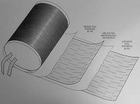
I've not yet noticed any specific feature (or group of features) that allows it to 'easily achieve low inductance'. What am I missing?
Flash Of Inspiration....
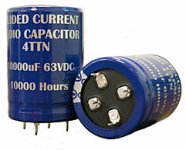
Lot's of claims about these....DNM Products - Capacitors (overview)


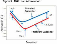
''In tests under load, the 4TTN capacitor's ability to attenuate
is 11dB better than a two terminal capacitor and this extra
performance is maintained up to extremely high frequencies''
Has anybody tried photoflash capacitors as local decoupling...I believe they exhibit very low series inductance.
Indeed, standard electros won't work for flash tube application.
Dan.
Lot's of claims about these....DNM Products - Capacitors (overview)


''In tests under load, the 4TTN capacitor's ability to attenuate
is 11dB better than a two terminal capacitor and this extra
performance is maintained up to extremely high frequencies''
Has anybody tried photoflash capacitors as local decoupling...I believe they exhibit very low series inductance.
Indeed, standard electros won't work for flash tube application.
Dan.
Last edited:
I used the parallel sheets of copper separated by insulation technique for the gainclone supplies - it all followed, once very low impedance had been achieved via the local caps it made no sense to throw away that away through poor final connections, and power and earthing planes were the obvious choice for that last step.I've not yet noticed any specific feature (or group of features) that allows it to 'easily achieve low inductance'. What am I missing?
Lot's of claims about these....DNM Products - Capacitors (overview)
View attachment 425501
View attachment 425502
View attachment 425503
''In tests under load, the 4TTN capacitor's ability to attenuate
is 11dB better than a two terminal capacitor and this extra
performance is maintained up to extremely high frequencies''
Has anybody tried photoflash capacitors as local decoupling...I believe they exhibit very low series inductance.
Indeed, standard electros won't work for flash tube application.
Dan.
Both Photo-flash and screw terminal caps are designed to handle high current usage. The peak current of a cap discharged into itself is VERY high with low esr and will void warentees on caps. The photo-flash connections inside and the thicker plates are made to handle repeated high current pulses. The scew terminal electrolytic is for high ripple current applications and the same internal connections, thick plates and heat sinking from plate to case etc are part of the design.
THx-RNMarsh
I used the parallel sheets of copper separated by insulation technique for the gainclone supplies - it all followed, once very low impedance had been achieved via the local caps it made no sense to throw away that away through poor final connections, and power and earthing planes were the obvious choice for that last step.
How did you connect between parallel sheets of copper and an LM3886 IC? If I recall correctly the LM has two power pins of one polarity and one of another. They aren't adjacent to one another so how did you go about minimizing the loop area?
BTW --- via L-T-C-Re-L.... it appeared the point of diminishing returns in a PA PS is 100K microfarads.... [for the fixed transformer/Amp size used.]
I have no idea about the details but it seems you cant get enough C there. Note, a common value is 10K mfd. 10K seems to take care of the ripple issue (along with the PSRR) but, as JC said, other factors are affected as well.
-RM
Surely that size is also governed by what is required at the output, Richard?
10,000 uF might be fine for an amp delivering no more than say 50W into no less than say 6 Ohms, with a mild phase shift.
But for 100W peaks into 3 Ohms with a -60 degree phase shift it is hardly likely to be enough.
Lot's of claims about these....DNM Products - Capacitors (overview)
They're fine if the aim is to attenuate incoming noise (say mains ripple). That's the easy part and can be done with series L or R without any fancy caps. But they're no better than normal caps for reducing load induced ripple on the supply (which is a much harder nut to crack).
- Status
- Not open for further replies.
- Home
- Member Areas
- The Lounge
- Sound Quality Vs. Measurements