Bias problem
I am posting a slightly updated schematic. Fixed a few errors.
Oops, no I am not, for some reason it won't let me. If a mediator reads this, can you help?
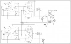
My current problem is biasing. Tubes 3 and 4 won't come together when I adjust the bias. If I get tube 3 to the proper 40mA, tube 4 runs 35.5mA and they maintain this 4.5mA separation no matter what I do.
In regard to the schematic of the bias circuit, it is like the second one I posted but there really is not a capacitor between the pot and the grid resistor, only one to ground.
It is not the tubes. They are reliably matched and this problem exists whichever tube is in the 4 position. I have tested all the components in the bias circuit and they are equal and I have even pulled the bias pot and it tracks fine. Plate voltages are equal (quiescent) in all tubes at 372V, both sides run on the same bias voltage source and there is no problem with tube positions 1 and 2 regardless again of the tube.
Any thoughts?
I am posting a slightly updated schematic. Fixed a few errors.
Oops, no I am not, for some reason it won't let me. If a mediator reads this, can you help?
My current problem is biasing. Tubes 3 and 4 won't come together when I adjust the bias. If I get tube 3 to the proper 40mA, tube 4 runs 35.5mA and they maintain this 4.5mA separation no matter what I do.
In regard to the schematic of the bias circuit, it is like the second one I posted but there really is not a capacitor between the pot and the grid resistor, only one to ground.
It is not the tubes. They are reliably matched and this problem exists whichever tube is in the 4 position. I have tested all the components in the bias circuit and they are equal and I have even pulled the bias pot and it tracks fine. Plate voltages are equal (quiescent) in all tubes at 372V, both sides run on the same bias voltage source and there is no problem with tube positions 1 and 2 regardless again of the tube.
Any thoughts?
How closely are your cathode resistors matched? If one is off by a single Ohm you'll get the readings you getting.
Craig
Craig
I am pretty sure they are no more than 0.1or 0.2 apart, but good point, 1 ohm is 10% which is 4mA. Hmmmmm.....
I will check this one again to make sure I was paying attention.
I will check this one again to make sure I was paying attention.
That's the only explanation I can think of if it's not the tubes. I've never seen this cause a problem but check the primary resistance of the OPT, CT to anode. If one side is WAAAAAAAYYYYYY off that might cause your mysterious readings.
Craig
Craig
Thanks. I can't think of any other possibilities either, so I will carefully recheck the resistors. then i will mod the circuit to individually bias the tubes...unless there is a reason I shouldn't. Seems that it should only take one new pot and cap per channel.
Tonight maybe, sigh. Work before play....
Tonight maybe, sigh. Work before play....
jrenkin, (If I see this right) you better relook at the screen tranny pnp with zener pulldown: you have to limit the eb current otherwise zap.
others agree ?
richy
others agree ?
richy
I could have the transistor wrong. What exactly do you mean? What is limiting the eb current? This has been working without problem so far, so if it looks wrong, it is probably my interpretation of the circuit since I really don't know what kind it is. I will look at it again when I check the cathode resistors.
I don't want "zap"....sounds bad.
I don't want "zap"....sounds bad.
The screen cap multiplier circuit using the npn (which it is) shown by SY is correct: The arrangement shown on your very first diag is shown different and incorrect. spot it !
richy
richy
So the transistor in the schematic Sy posted for me is correct then.
Why do you call it a "screen cap multiplier"? I thought is was more of a constant voltage dropping device.
What if I just took that out and connected triode with a 100R screen resistor?
Why do you call it a "screen cap multiplier"? I thought is was more of a constant voltage dropping device.
What if I just took that out and connected triode with a 100R screen resistor?
The gain of the pass transistor at the throughput current, multiplied by the ext capacitance connected on the transistor base. That's the equivalent cap seen at the emitter. Quite effective.
With mosfets it's even more fantastic, but needs protection.
With mosfets it's even more fantastic, but needs protection.
This is not a cap multiplier but a classic emitter-follower regulator. The cap serves to reduce zener noise.
That make sense, thanks.
So what is a "cap multiplier"? I know a few things that are "fantastic, but needs protection", and could always learn a few more....
So what is a "cap multiplier"? I know a few things that are "fantastic, but needs protection", and could always learn a few more....
analog_sa; SY screen feed pass circuit doesn't contain zener diodes, or does it ? they are quite faint on the schematic.
They are not drawn as zeners because I really don't know what they are.
They are tiny glass diodes and I can't read what they are even with a magnifying glass.
Should they be zeners? What kind would be best in this application?
I admit I don't know much about diodes...
They are tiny glass diodes and I can't read what they are even with a magnifying glass.
Should they be zeners? What kind would be best in this application?
I admit I don't know much about diodes...
They have to be zeners, just measure the DC voltage across each of them or both of them and I'll bet the total is close to your screen voltage. The 75K resistor supplies the current for them. How did the cathode resistors turn out?
Craig
Craig
Just tested them. My cheap DVM seems to only be accurate to +/- 0.3R which makes matching 10R resistors tough. It looks like the current resistors are 0.5R to 0.8R apart and given the inaccuracy of the DVM is probably adequate as an explanation.
I have some that match at 10.3ishR and seem to fluctuate on the DVM in the same manner, so when I have time I will swap them out and try the bias again.
Might be a bit, this weekend's for skiing!
I have some that match at 10.3ishR and seem to fluctuate on the DVM in the same manner, so when I have time I will swap them out and try the bias again.
Might be a bit, this weekend's for skiing!
I replaced the resistors with better matched ones. Improved the bias a bit, but not as good as I like. I will try with what I think is a better matched set of tubes. If that isn't right, I will rewire with individual bias adjustment for all 4 tubes. seems like that is a better way in any case.
A simple input question.
I have finally decided to rework the front end, taking out the 6U8 and adding 1/2 of a 6SL7 followed by a 6SN7 in LTP (i think) like the modified Eico circuit.
the simple Q: Is there anything wrong with using 1/2 of the same 6SL7 for each channel rather than 1/2 of a whole one for each? That would let me add only one hole to the pre-built chassis this amp was originally made with.
I guess, also, I haven't seen this with the 6SL& halves used in a cathode follower. Any point in that?
- Status
- Not open for further replies.
- Home
- Amplifiers
- Tubes / Valves
- Sophia Electric EL34 Schematic