I have finally worked out this schematic as an exercise to learn about amps.
There are a number of things i am not so sure about and would appreciate any help.
1. I can't read any of the diode values (damn eyesight). how can I figure out what they are and how much does that matter?
2. I don't really understand the g2 voltage circuit. Any help?
3. I might be able to eventually figure this out, but what is the purpose of the capacitor between pins 7 and 3 of the first stage?
4. there is a relay circuit to switch between input sources. Is this really necessary?
5. Thinking of modifacations to improve and to learn more about the amps function. Certainly upgrading caps, Triode strapping and small adjustments in negative feedback would be easy. Any other thoughts for this circuit?
Sorry if i am not that good at drawing schematics....
Attachments
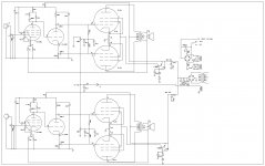
Sophia Electric EL34 revised
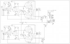
Ok, second try. Many errors in the first post. I have updated the schematic and replaced some values. Interestingly I note that the NFB resistor is only 68 ohms. Seems like a lot of feedback to me.
still looking for input. Thanks!
Ok, second try. Many errors in the first post. I have updated the schematic and replaced some values. Interestingly I note that the NFB resistor is only 68 ohms. Seems like a lot of feedback to me.
still looking for input. Thanks!
Attachments
Well, that circuit is just a copy of the Dynaco Mk. III.
See: http://www.triodeel.com/dynamk3.gif
There are some "updates" as you have observed.
First, I would stick to the Dynaco power supply arrangement with the 5AR4 tube. The Sophia schematic assumes you will select the diode bridge based upon the voltage and current requirements of the amp. The choice is yours, but it obviously does matter.
The G2 arrangement is a screen grid regulator. This will be irrelevant if you use an output transformer with ultralinear taps. Otherwise triode connect the screen grids or go with the screen regs. for most power and bass.
The screen grid of the first tube, the voltage amp, is bypassed to its cathode. Again, see the Dynaco schematic for a better implementation of the same thing. Alternatively, you could replace the pentode with a 12AT7 for better sound and easier implementation. You are going to have to determine the feedback resistor anyway.
No relay is necessary.
You will have to determine the negative feedback for yourself. It is related to many factors in the amp so will change as you adjust components. Measure the voltage in and the voltage out with no feedback. That is your open loop gain. Now connect a 10k pot (or what ever is appropriate to get you in range) in the feedback loop without changing the signal level into the amp. Adjust the pot for one half the original voltage, that's 6dB; one quarter the original voltage = 12dB; one tenth the original voltage = 20dB. Measure the resistance of the pot for these feedback levels. Now replace the pot with fixed resistors and listen. Change the feedback resistors and see which gives the sound you prefer.
Sorry, I thought it was KT88 output tubes. Since it uses EL34 tubes, it is a copy of the Dynaco ST70 not the Mk.III.
See: Dynaco ST70 Tube Amplifier Schematic
See: Dynaco ST70 Tube Amplifier Schematic
Thank you so much for your reply. I will research this well known amp to help me understand the Sophia one. I appreciate your suggestions.
I had the same plan to work with t he NFB as well. do you think I should try a small capacitor in parallel?
Also, do you feel that it is odd that the current NFB resistor is so low, 68 ohms?
Also, if you look at my second schematic, there are my measured voltages. They are quite discrepant. Should i be making adjustments to fix that?
this is an already constructed amp, so no ultralinear taps available. I will try Triode and compare with the regulated g2.
Do you really think that it is worth re-engineering the power supply to use a rectifier tube rather than SS?
Is it simple to replace the 6U8 pentode with a 12AT7, or would I need to re-engineer the forst stage as well?
thanks again.
I didn't realize this was a commercial product that you already owned. I though that it was a schematic you had found that you were going to use to build an amp. As such, certainly the points about changing the power supply don't apply. If the screen grid regulators are already engineered and installed then they are fine too. I just thought the regs. added complexity that wasn't warranted for a scratch build where ultralinear or triode might be preferable anyway.
You can definitely try the triode connection but it will be more complicated than just installing a 100 ohm resistor between SG and plate. I would disconnect the supply to the screen regulators so they are out of the circuit completely. That would mean disconnecting the pass transistor from the B+ as well as its bias resistor.
To replace the 6U8 would require another tube socket. Again I thought this was a scratch build.
As for the feedback, if the amp is working well then you can leave it as is. If not you can use the method I describe to dial in the feedback you like. You will need an oscilloscope to determine the best value of cap to parallel the feedback resistor. Using your signal generator set to square waves, try for the best looking square waves at about 1000Hz. Starting with 68pf add capacitance (100pf, 150pf, 200pf) until there is no ringing or over shoot on the square wave.
As for the voltages, I can't read them very well, but it looks like you may be referring to the 6U8. If the resistor values match channel to channel you will need to find two 608 tubes that match in circuit.
So, I would say that since this is a commercial product, it would be better to leave it as is. If you really want to modify and improve some gear while learning about tube amps, I would think that the Triode Electronics Dynaco ST70 kit would be the best place to start. While there are certainly a few different ST70 kits available, I would much prefer the Triode one. The ST70 like your Sophia uses a pentode/triode front end, but Dynaco used a 7199 tube instead of the 6U8. Both the 6U8 and 7199 are compromises both technically and sonically. The Triode kit breaks the pentode/triode into two different tubes so that you now can choose the pentode and the triode that you prefer. I believe the kit also has instructions on how to convert to a 12AT7 voltage amp.
Thanks again. yes, I did get this working, but beat up, production EL34 amp to learn by rebuilding. Kind of like a kit, just pre-built and in a condition that it doesn't need to be left as is (I certainly don't need the amp, I am playing a Sophia Electric KT88 early version amp I bought damaged and fixed, have a great Forte 55 SS amp upgraded by Jon Sodergberg and a McIntosh 2105 bought broken, fixed then upgraded). I have too many!
It has been nearly 20 years since my days working in high voltage laser and switching electronics (all SS), and I never was that proficient or knowledgeable. So it seemed to be as good a way as any to get my feet wet again.
By drawing the schematic from the circuit and reading, I have already learned a lot.
Now i am nearly ready (if I could stop this damn home remodel...) to continue to learn by doing.
I have a nice chassis, all the parts and a base circuit I am starting to understand, I can work with upgrades and modifications and re-learning to use an oscilloscope. It is not really about producing and amp, it is about learning how all this stuff goes together, why, and then how to make it sound great and listen to beutiful music on something I have worked on myself.
I want to basically take it apart and re-build it with point to point wiring (just to learn how to do this), adjust the NFB to my liking, upgrade signal caps and power supply caps and what ever else i feel like. oh, and repaint the chassis...
then i will hopefully understand enough to perhaps modify the circuit. that might be a good time to build in a two tube input stage or the 12AT7 or similar tube. Or maybe I will give up and get that kit someday...
Your input and suggestions are very helpful and are helping me get past a recent block in understanding and where to go next. Since I will be moving at a snails pace in this experience, i guess I will periodically update my progress and questions here. If you have the time and patience, any help would be appreciated. thanks!
OK, now I have the big picture. That's a great idea starting with an amp that you can modify any way you want. I have no idea what it looks like but if there is the possibility to punch another tube socket or two I would definitely do so. At the very least do away with the 6U8 and use a EF86 and 6CG7 as the front end.
Have fun.
Have fun.
Thanks! Using a 6cg7 is a good idea and I happen to have a few laying about.
I was also thinking about seeing if I can punch a few hole. I may, but it is a proprietary chassis, so may not lend itself to such modification easily. I have the tools, so it can be done if there is room.
That gives me two steps for modification, first a new tube, so I can learn to determine the appropriate values of components. Then a two tube mod and a more complicated reworking. Cool!
Any suggestions on where to learn about voltage and current regulation? I really don't understand the g2 reg. Just ignorant of simple transistor and diode circuits I guess.
Thanks again!
Pentodes and beam power tubes work best with a stable screen grid. Your amp has a regulator to maintain a constant voltage on the screen. It consists of a pass transistor and a reference voltage. The transistor is biased by the base/emitter resistor and the base is sitting on the reference voltage which is a stack of zeners.
Here is a good site for a refresher course in electronics:
http://www.freewebs.com/valvewizard/ccs.html
Here is a good site for a refresher course in electronics:
http://www.freewebs.com/valvewizard/ccs.html
Well, I am not sure. the numbers are SN1 13005. i think I have the leads right, but I will recheck.
I believe it should be an NPN with the collector going to B+ and the emitter going to the screen grids. The base "sits" on the voltage reference.
I guess that would make more sense. Thanks! I need to study that stuff a little more....
Hey, do you know how to figure out the values of those zener diodes (and other diodes)? I can't read the tiny print on them.
Hey, do you know how to figure out the values of those zener diodes (and other diodes)? I can't read the tiny print on them.
For the zeners, just measure the voltage drop across them. For the PS you need to ensure that they meet the peak inverse voltage and current requirements of the amp.
I have another feedback question.
It seems that the resistor/capacitor bypassing the input tube plate limits the frequency output of the pre-amp tube to prevent ringing in the feedback circuit. This is instead of a feedback resistor bypass capacitor, which would prevent ringing in a different way.
The question is: which is better? Or should I try both? Even at the same time?
I presume the values of 47k and 100pF are specific for the feedback resistor, which is only 68R which seems like an enormous amount of feedback.
So as i change the feedback resistor, I can eliminate the current frequency limiting circuit and add and appropriate bypass capacitor, or i can (and will have to) figure out new frequency limiting values for the current circuit.
Or am I out of line....
68r ain't nothing but a number. The actual feedback is much more complicated than that.
Notice first that the 68r resistor is part of a voltage divider with another 68r resistor that essentially divides the feedback signal in half. Then you have the 68r resistor in series with the 1k resistor making it about 15% of the total cathode resistor. So now we have divided the signal in half and then applied just 15% of that to the cathode as feedback.
To change the amount of feedback could require more than just changing the value of a resistor. As you add resistance to that 68r resistor you are also changing the operating point of the first tube. That 68r resistor is in series with the secondary of the output transformer and in parallel with the other 68r resistor making it part of the cathode resistor of the first tube as well. I would guess that you could change the 68r resistor to 100r and up to 1k to see what would happen. I don't think it would substantially affect the operation of the pentode. If you start to add more resistance, then you will have to take into account the other 68r resistor and the 1k cathode resistor and ensure the pentode is properly biased.
The 47k resistor and 100pF cap are feedback intended to eliminate ringing in the output transformer and are specific to that transformer. I would leave them exactly as employed by the design engineer. If you redesign the front end, then you would test with square waves at 10kHz to see what works best with the new front end.
In the end I think the most practical mod would be to punch another hole in the chassis, change the first tube to a 12AT7 w/ 100k plate load, with the feedback directly to the cathode, driving a 6CG7 w/ 47k plate and cathode resistors as the paraphase splitter.
Good luck. I think that the more you delve into this, the more you will find that the person who designed this amp did so by looking at the amp as an integral whole. Once you start to modify it, you will have to do the same thing: consider the entire circuit and the ramifications of changing any one component.
more schematics
Here is an excellent thread discussing pentode front end with paraphase and LTP splitters. Check out each of the schematics for different ideas on feedback and pentode front ends.
Tube DIY Asylum
Here is an excellent thread discussing pentode front end with paraphase and LTP splitters. Check out each of the schematics for different ideas on feedback and pentode front ends.
Tube DIY Asylum
- Status
- Not open for further replies.
- Home
- Amplifiers
- Tubes / Valves
- Sophia Electric EL34 Schematic