What's the DC voltage on the collector of Q909?
With the 100Hz sine wave, post a photo of the waveform on the base and the emitter of Q909.
With the 100Hz sine wave, post a photo of the waveform on the base and the emitter of Q909.
To confirm is this with respect to power gnd, or speaker -ve?With the 100Hz sine wave, post a photo of the waveform on the base and the emitter of Q909.
Ok I got 60mv when first connected and this rose upto 200mv, and was still rising, pretty fast.
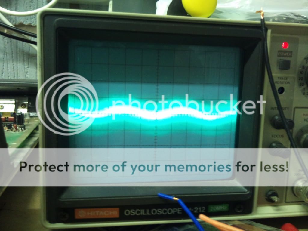
When I first turned on the amp the waveforms were more pronounced on the emmiter side, then this diminished to this:
There was a lovely peak literally a top half of a waveform, then this quickly dropped to the above
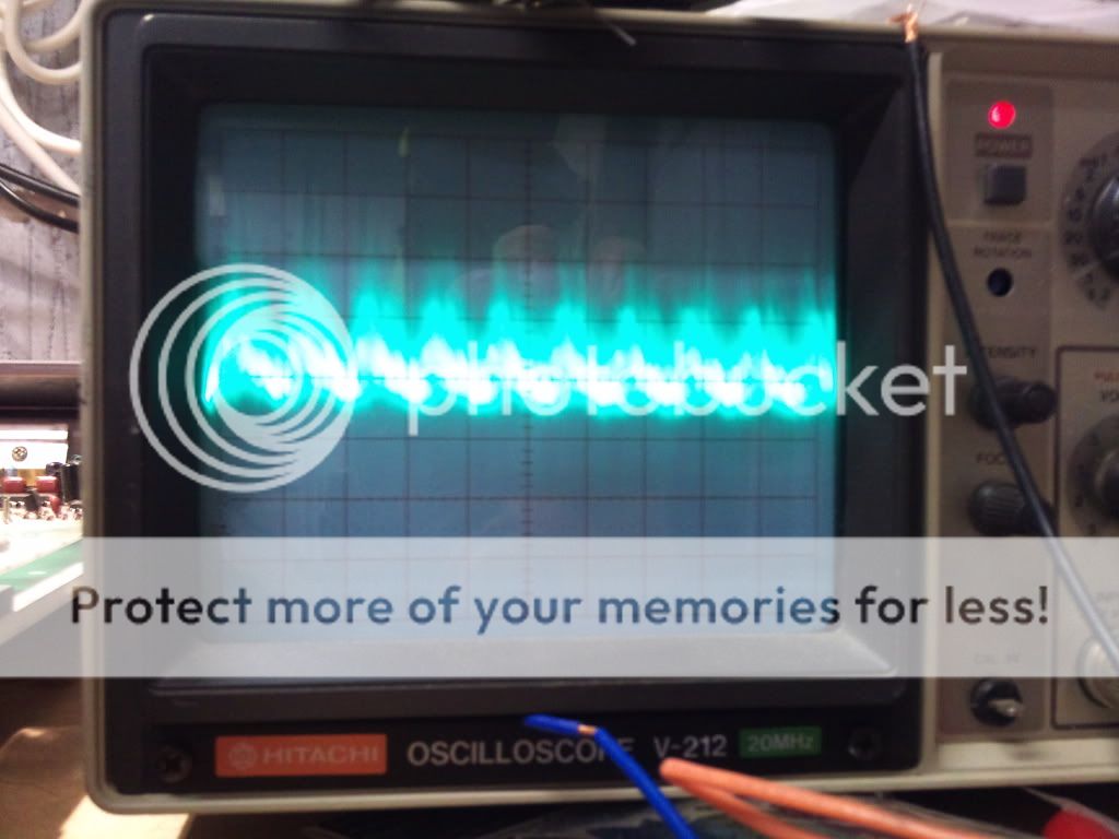
On the base side I got this:
When I first turned on the amp the waveforms were more pronounced on the emmiter side, then this diminished to this:
An externally hosted image should be here but it was not working when we last tested it.
There was a lovely peak literally a top half of a waveform, then this quickly dropped to the above
On the base side I got this:
An externally hosted image should be here but it was not working when we last tested it.
Ok, here we go:
10mv div
10m(like 'mew')s
Base:

Emmiter:
It's just noise I think?
I get 10v on base side and 1.6v emmiter side... DC
Edit: I forgot to add these waveforms and voltages do NOT change, whether there is a tone playing or not...
10mv div
10m(like 'mew')s
Base:
Emmiter:
It's just noise I think?
I get 10v on base side and 1.6v emmiter side... DC
Edit: I forgot to add these waveforms and voltages do NOT change, whether there is a tone playing or not...
Last edited:
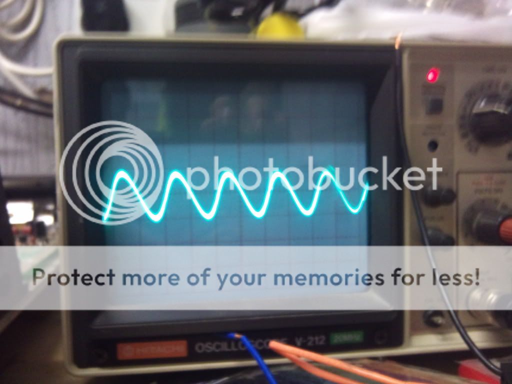
I might be about to drop one here, I think... Well here is a current 100hz tone...
Without any load on the amp. I'm about to try another speaker... 😛😀
EDIT:
Nope...
Here is the waveform with a speaker in:
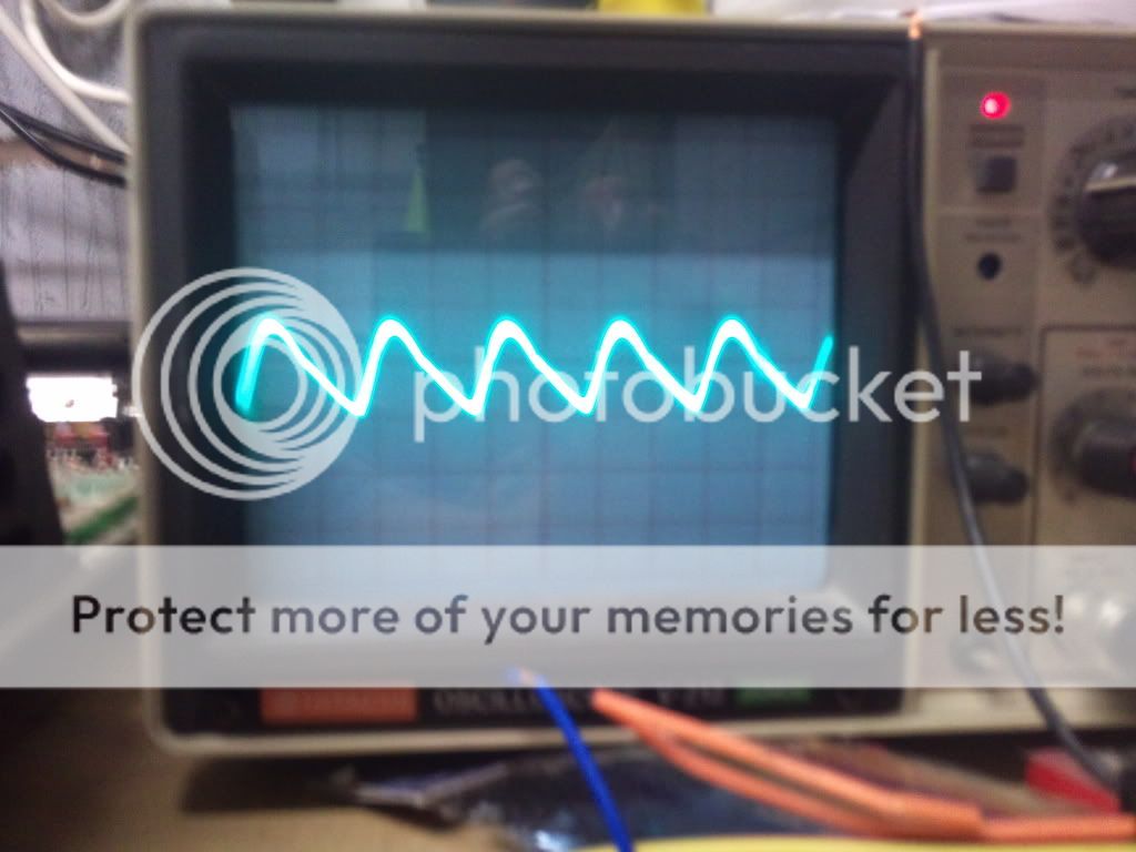
And without:
Without any load on the amp. I'm about to try another speaker... 😛😀
EDIT:
Nope...
Here is the waveform with a speaker in:
And without:
Last edited:
In post #40, only the top was distorted/clipped badly. What have you done to the amp since then?
The waveforms in post #47 are just noise. You'd set the timebase to about 2ms. You'd set the vertical amp to whatever is needed to capture the waveform (approximately the same as you used above). Always post the timebase and vertical amp settings when you post images of the waveforms.
The waveforms in post #47 are just noise. You'd set the timebase to about 2ms. You'd set the vertical amp to whatever is needed to capture the waveform (approximately the same as you used above). Always post the timebase and vertical amp settings when you post images of the waveforms.
Ok, the only thing I have done is bend over Q909 a little so I could reach the legs to pop the probe across. I have changed nothing else.
I don't know if there is a loose connection somewhere on 909?
I tried other timebases and V/div's for testing 909, however I got nothing but a flat line, which didn't change when a tone was played.
I don't know if there is a loose connection somewhere on 909?
I tried other timebases and V/div's for testing 909, however I got nothing but a flat line, which didn't change when a tone was played.
Look at the signal for the same drivers for the other channel. Confirm that they look like the output signal.
Ok, on the other channel (left side) I get the same deadline, with a little noise.
However I may be having the black probe on the wrong part....
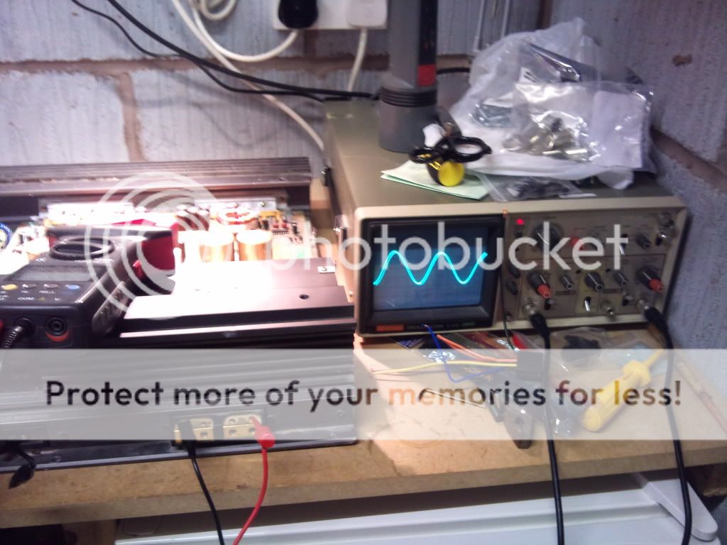
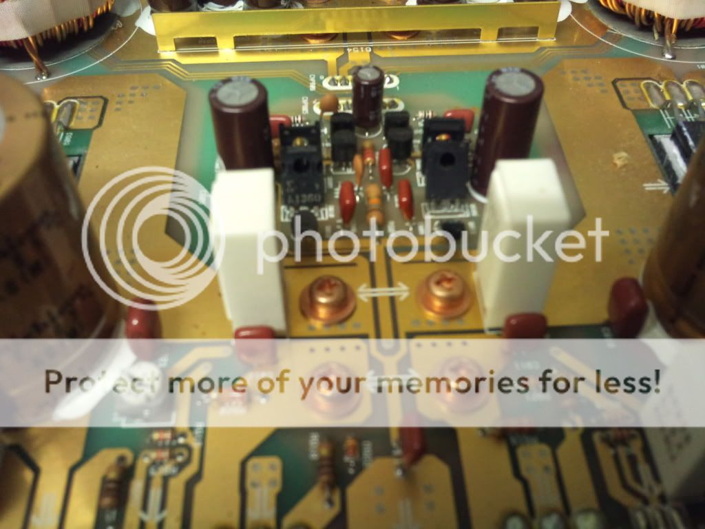
Here's a pic of what i'm doing. The 4 screw heads i'm using as the gnd probe. From the top left I get a waveform on both the bas and emmiter of both left and right channels, however, on the bottom left I get nothing but the noise as descibed above... The bottom left has perfect conductivity with the -ve speaker terminal.
However I may be having the black probe on the wrong part....
Here's a pic of what i'm doing. The 4 screw heads i'm using as the gnd probe. From the top left I get a waveform on both the bas and emmiter of both left and right channels, however, on the bottom left I get nothing but the noise as descibed above... The bottom left has perfect conductivity with the -ve speaker terminal.
Connect the black prove/scope ground on the non-bridging speaker terminal for the channel being tested. Make the connection outside of the amp.
Ok, thanks. Left channel I get the waveform the same on outputs.
Right channel I get a flat line (albeit some noise) on both base and emmiter.😱
Right channel I get a flat line (albeit some noise) on both base and emmiter.😱
64v emmiter
9.85v collector
63v base
Also I get the waveform on both emmiter and base. (I just guessed that would be the next question.)
9.85v collector
63v base
Also I get the waveform on both emmiter and base. (I just guessed that would be the next question.)
Last edited:
Look at the signal on Q905 in the good channel. Which pins have signal (likely only the collector).
Only collector, like you said...
The base and emmiter there have nothing. I rechecked and for certain the 'faulty' channel does have a waveform on all 3 legs.
The base and emmiter there have nothing. I rechecked and for certain the 'faulty' channel does have a waveform on all 3 legs.
If it has signal on the collector of the defective channel, you should have signal on the base of Q909. Confirm that you have continuity between the collector of Q905 and the base of Q909.
- Status
- Not open for further replies.
- Home
- General Interest
- Car Audio
- Sony xm2000r - Guzzling power, need to trace the problem.