All the outputs test fine in this amp ..
When trying to power up the amp I get a pulse of 30 volts of DC across all 4 channels ..
Any ideas what might cause this ?
Sorry for the pictures my internet is down right now so posting from my phone
When trying to power up the amp I get a pulse of 30 volts of DC across all 4 channels ..
Any ideas what might cause this ?
Sorry for the pictures my internet is down right now so posting from my phone
When the amp powers up for a sec I get both + and -15 volts on all
Opamps..
I checked the rectifiers and no broken legs they also test good..I checked for shorts to the heat sink and found none ..
Amp is still pulses DC out of the speaker terminals
Opamps..
I checked the rectifiers and no broken legs they also test good..I checked for shorts to the heat sink and found none ..
Amp is still pulses DC out of the speaker terminals
To clarify... All bridging speaker terminals go to +30v but all non-bridging terminals remain at 0v. Is that correct?
Yes all bridging speaker terminals go to + 30 volts..
All non bridging speaker terminals remain at 0.00 volts
All non bridging speaker terminals remain at 0.00 volts
Yes when i try to power the amp up I get -25 volts on half of the output transistors.. I get + 25 volts on the other half of them
.
.
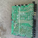
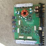
When you get back online, post photos of both the top and bottom of the board. I don't have this service manual but I may have something close enough.
I can't find anything close to the circuit in this amp. I'd like to disable the protection circuit but I can't tell you how to easily do that without a diagram. If you post the voltage on the power supply IC, it may be possible to make an educated guess to disable the protection.
Pin 1:0.00
Pin 2:2.50
Pin 3:4.78
Pin 4:0.32
Pin 5:1:45
Pin 6:3.74
Pin 7:0.00
Pin 8:13.87
Pin 9:0.46
Pin 10:12.11
Pin 11:13.88
Pin 12:13.88
Pin 13:4.88
Pin 14:4.88
Pin 15.4.88
Pin 16.13.88
Pin 2:2.50
Pin 3:4.78
Pin 4:0.32
Pin 5:1:45
Pin 6:3.74
Pin 7:0.00
Pin 8:13.87
Pin 9:0.46
Pin 10:12.11
Pin 11:13.88
Pin 12:13.88
Pin 13:4.88
Pin 14:4.88
Pin 15.4.88
Pin 16.13.88
Disconnect whatever is driving pin 16 from pin 16 and connect pin 16 to pin 7. Be careful when powering it up.
I'm assuming that pin 10 is an error. If not, the amp should be drawing excessive current.
I'm assuming that pin 10 is an error. If not, the amp should be drawing excessive current.
Pin 10 is not an error I checked it 3 times ..
So before I disable the protection should
I check around to see why pin 10'is high
So before I disable the protection should
I check around to see why pin 10'is high
If this amp has a normal power supply, pin 10 should cause about the same voltage to appear on the gates of the FETs (if the drive circuit isn't damaged). That should drive 1/2 of the FETs fully on, causing the amp to draw excessive current.
If leg 1 of the PS FETs is near 12v, leg 3 is at ground and the center leg is near B+ voltage, the FETs are blown.
If leg 1 of the PS FETs is near 12v, leg 3 is at ground and the center leg is near B+ voltage, the FETs are blown.
I removed all of he power supply fets and tested them
They test fine in and out of the board ..
After removing them from the amp I get the following voltages on the pads for the power supply fets
Gate:4.97
Drain:13.88
Source:0.00
On the 594 I get
Pin 1:0.00
Pin 2:2.51
Pin 3:0.05
Pin 4:0.33
Pin 5:1.44
Pin 6:3.73
Pin 7:0.00
Pin 8:13.89
Pin 9:5.86
Pin 10:12.99
Pin 11:13.89
Pin 12:13.89
Pin 13:4.98
Pin 14:4.98
Pin 15:4.98
Pin 16:0.01
Could this IC possibly be defective?
Do you get 5v on all of the gates? It would be more likely that you would have 12v on half of the gates with 12v on pin 10.
Yes, the IC could be defective. It's also possible that something is pulling the output (pin 10) high.
Yes, the IC could be defective. It's also possible that something is pulling the output (pin 10) high.
It appears that one of the driver transistors is defective ..
It is marked LE ..
It is the same package size as the JL audio power supply drivers ..
Is the a good sub for this ?
It is marked LE ..
It is the same package size as the JL audio power supply drivers ..
Is the a good sub for this ?
I can't find the LE mark on any sites.
Is the collector (center leg or tab) connected to B+ or to ground?
Is the collector (center leg or tab) connected to B+ or to ground?
- Status
- Not open for further replies.
- Home
- General Interest
- Car Audio
- Sony XM-GS400