On the 4 jumpers from left to right I have
Jw608: -3.88vdc
Jw607: -15vdc
Jw606: 15vdc
Jw605: 0vdc
All the solder joints looked fine
Jw608: -3.88vdc
Jw607: -15vdc
Jw606: 15vdc
Jw605: 0vdc
All the solder joints looked fine
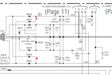
Check the DC voltage on the points indicated A and B. Check all 4 diodes connected to those points.
When the amp is in operation, you should have ±45v there.
This is the full SM if you want it.
http://www.bcae1.com/temp/sony - XM-7547_Car Power Amplifier SM.pdf
When the amp is in operation, you should have ±45v there.
This is the full SM if you want it.
http://www.bcae1.com/temp/sony - XM-7547_Car Power Amplifier SM.pdf
Attachments
maybe I'm on the wrong jumpers because the 4 jumpers I am measuring seem to be correct.
Jw608 is measuring 3.3 and is labeled fan control
Jw606/7 are +/- 15v
Jw605 is labeled ground
All measurements are good.
Jw608 is measuring 3.3 and is labeled fan control
Jw606/7 are +/- 15v
Jw605 is labeled ground
All measurements are good.
Now you need to check further down the line.
Check the ±15 at the op-amps.
Check the ±45 at the jumpers JW638 and JW639.
Push on the board to flex it slightly while checking the voltage.
Check the ±15 at the op-amps.
Check the ±45 at the jumpers JW638 and JW639.
Push on the board to flex it slightly while checking the voltage.
What's the resistance from 638/639 to the ±45v rectifiers on the low-voltage supply?
The op-amps obviously can't work from 0.8v. Find the break.
The op-amps obviously can't work from 0.8v. Find the break.
I don't see any components that would fail and break the circuit so you're going to have to trace the circuit and find the break. Mark it with a sharpie as you go if it's hard to follow.
- Home
- General Interest
- Car Audio
- Sony xm-7547