Parallel output devices would give a lower output impedance, especially if
the bias current is allowed to be higher.
😎
the bias current is allowed to be higher.
😎
... And the capacitance would be double, so would the recommend minimum output impedance halve? I think I am more than good there, whatever is before the amp will be an active crossover which will have a buffer at the end.
Good afternoon Mr Pass,
One question related to the answer of Mr Luvdunhill paralleling the CSX1. I consider but is my taste or my idea that the paradigma of this kind of circuits is the simplicity and this circuit is quasi magic for my goals. And paralleling the out devices we can improve the damping for uses the amp with another more complex loudspeakers, that is no my case cause i use full range high sensitivity back horn loaded speakers.
Luckily I got a good matched Vfet from Acroman
Must we use ballast resistors in the sources of the Vfet for equalize the current? I trying to make this amp but my only problem was the high capacitance of g-s.
Thanks in advance, please receive my best regards and the grateful for share your treasures.
The best for the rest of the gentlemen.


What are the thermal requirements for the heatsinks? K/W?
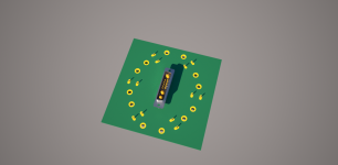
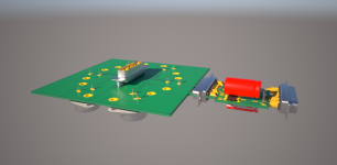
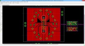
The POWER LEFT/RIGHT parts of the amplifier are connected with following BRIDGE to the AMPLIFIER part (SMD or THT are possible).
The choice of the heatsinks defines the dimension of the overall amplifier: you choose 300mm and 5U then the deepth is 300mm and the height 5U minimum (the POWER LEFT/RIGHT PCB is centrally mounted: I suppose the heat is radiated from the FET´s away; some FLIR measurements should be nice and helpfull).
Attachments
The 5u case is built on 2 heatsinks joined together on each side of the amp.
So keep that in mind when determing best way to space the output mosfets evenly.
So keep that in mind when determing best way to space the output mosfets evenly.

Normally we put gate resistors on the board that the output mosfets are mounted on (not on the motherboard).
Then you have more freedom.
Then you have more freedom.
I know, but no components except mosfets in the power part, thats the challenge!
Tomorrow I will finisch with the routing auf the voltage amplifier part. Then I will start the mechanical construction...
Tomorrow I will finisch with the routing auf the voltage amplifier part. Then I will start the mechanical construction...
challenge or not , leaving deliberately those gate resistors far from gates is simply stupid

they're called gate resistors with reason ; on contrary , we could call them city hall resistors .... or nearest lake resistors ......... or Schwartzwald resistors .........

they're called gate resistors with reason ; on contrary , we could call them city hall resistors .... or nearest lake resistors ......... or Schwartzwald resistors .........
You will see on the schematic, Sony mosfets have 221 Ohm gate resistors and Irfp240 have 1k gate resistors.
I just keep wondering why he is building an Silicon Graphics (SGI) peripheral! I could use those CAD skills to generate a drill pattern to pack a bunch of TO-3 devices on an aluminum angle, if he has some free time 🙂
I know, but no components except mosfets in the power part, thats the challenge!
This is not a good practice. The gate resistors must be as close to the gate pins as possible.
I know that the resistor should be so close as possible near the gate.
... take a look at Mr. Pass layout, or Tea-Bag´s layout: the resistors are not so close anyway...
Simple question: did the temperature have an influence of the behavior of this resistors? No, then I will place this 221R and 1k0 as short as possible near the gate!
... take a look at Mr. Pass layout, or Tea-Bag´s layout: the resistors are not so close anyway...
Simple question: did the temperature have an influence of the behavior of this resistors? No, then I will place this 221R and 1k0 as short as possible near the gate!
just put them close ........ they'll be colder than some other resistors in circuit , having some current through them .......
so , no worries
I know many Papa's pcbs ...... he's always placing gate resistors where they belong
so , no worries
I know many Papa's pcbs ...... he's always placing gate resistors where they belong
Jean-Paul,
You seem to have the skills, time and energy. It would be great if you designed boards that could be bolted to a L-shape or T-shape aluminum profile attached to a MF35-151.5 Conrad heat sink. Conrad Heatsinks - Products
The boards should accommodate 2 pairs of VFETs and use TO-247 package for the MOSFETs. The boards should also be symmetric single pieces, one for each channel, similar to what Nelson presented. I would be certainly interested in buying them.
- Home
- Amplifiers
- Pass Labs
- Sony vFET Amplifier Part 2