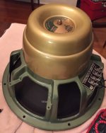
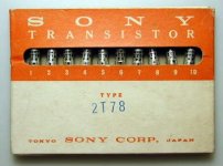
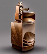
Really?
I still can't find the "latest" version of the original schematics (Was it updated since the original VFET2 pdf?), but if the differences between GB and Original are only things Nelson explained on the newest pdf, I though it's not too hard to utilize GB board as a basis of the original version...
I also was wondering what is the best way to deal with the extra pairs of VFET, which probably would require extra L-bar.
There is no cascode feedback, no provision for the global feedback switch, no bootstraping in the output mosfets so quite a few differences. It is doable certainly but not for the faint of heart!
Some members have developed boards for the original version.
Tea Bag did a GB some time ago:
http://www.diyaudio.com/forums/group-buys/285823-gb-pass-sony-vfet-version-2-al-boards-tea-bag.html
http://www.diyaudio.com/forums/group-buys/285823-gb-pass-sony-vfet-version-2-al-boards-tea-bag.html
Some members have developed boards for the original version.
Papa designed pcb's are super cute
show on original linked post :
http://www.diyaudio.com/forums/pass-labs/276711-sony-vfet-amplifier-part-2-a-35.html#post4401429
Best regards 🙂
Attachments
Sorry but what we can put for the 2SK2013/J313 ??
Possible FQP3N30, FQP3P20 as other Firstwatt amps. I know one USA supplier who claims to have orginal 2SK2013/J13's but as always with these obsolete parts I am somewhat skeptical unless they are tested.
From the Firstwatt BA3 build,
The 2SJ313 and 2SK2013 are still available, and you can use them or substitute other Mosfets, such as the Fairchild FQP3N30 and FQP3P20. The Vgs of the Toshibas is about 2 volts. Some of the alternatives will be in the region of 4 volts or so, requiring a higher value for P1 and P2, probably 1K ohm.
http://www.diyaudio.com/forums/diyaudio-com-articles/194809-burning-amplifier-ba-3-a.html
I will wait to read Jim's build instructions to find out what he used.
So - thanks to Nelson and the DIY-Audio-Team quite a few of us will get their hands on 4 pairs of V-Fets.
What should we do, build 2 pairs of the "The DIY Sony VFET" or use the FETs to build the original 2015 "VFET Part 2" Amp? 🙂
The PCB which is provided for, only supports two VFET's, one pair.
So if you want to do the original 2015 VFET pt2 you have to look for different PCB supporting two pairs.
Papa designed pcb's are super cute
show on original linked post :
http://www.diyaudio.com/forums/pass-labs/276711-sony-vfet-amplifier-part-2-a-35.html#post4401429
Best regards 🙂
Correct also real Papa PCB 🙂
Anybody from Germany who wants to share shipping costs?
Sven
Hi Seven, I am in Berlin and can share the shipping costs too!
Cheers,
Mamal
Stefan, Mamal: Its not really efficient to share between more than 3 people so I will contact you via PM and we will organize between the 3 of us.
Regards
Sven
Regards
Sven
Last edited:
Does anybody know what the colour of the PCB's are? Black as shown earlier by Papa?
They're black to match the brackets. I assume to use 2 pairs of VFETs per side you need a second bracket and short jumper wires to the VFETs on the first bracket.
Is it possible to use 2SK214/2SJ77 instead of 2SK2013/2SJ313, provided pinout difference and Vgs threshold are taken into account?
P.S Thanks for all the effort guys!
P.S Thanks for all the effort guys!
I have 2SK214/2SJ77 but no Toshiba parts, that's why I asked.
Thanks for that referral. I found some of these on Amazon, but much prefer to support DIYAudio folk - better items, matching, etc. He reserved my set quickly, and is easy to work with.
Now what are Q3-Q4?
Hi Sven, I am from Germany as well and would like to share shipping cost.Anybody from Germany who wants to share shipping costs?
Sven
Cheers Ernst
I have some pairs of toshiba 2sk2013/2sj213 mosfets available, if someone needs I could share a few.
Now what are Q3-Q4?
I asked this a while back.. it's your typical small signal bjt pair. Use whatever you have on hand.. or have seen in other FW cascoded front ends, like F5 turbo.
I asked this a while back.. it's your typical small signal bjt pair. Use whatever you have on hand.. or have seen in other FW cascoded front ends, like F5 turbo.
BC550/560 come to mind, as well as some other toshiba parts
I'd like to post a response to a question asked over email. The question being "What happens if I fry my VFETs?".
We haven't discussed it, but several items:
1) The design is conservative, and the initial testing procedure is
intended to catch issues and make adjustments before the VFETs get
installed.
2) I have pre-tested and measured the kit VFETs at power.
3) They are quite robust. I have not lost a single device in spite of the
usual mishaps on the bench and in the field.
4) An allowance has been made for a percentage of failed parts. Policy
for providing replacements has not been determined.
5) When all the VFETs are dead and gone, I have a procedure for
replacing them with ordinary Mosfets.
😎
- Home
- Amplifiers
- Pass Labs
- Sony vFET Amplifier Part 2


