Recently, while replacing electrolytic caps in my TAN-5550, I found 2 that had been installed in reverse polarity. Replacements were installed in correct polarity according to both schematic & PCB component layout diagram.
However, the schematic has always bothered me a bit, showing 2 pairs of caps being used in what appears to be the wrong polarity (at least to my limited understanding of all the finer details of electronic design).
I'm hoping an expert can comment on the circuit, and tell me if the schematic is correct or not. And if it is correct, why the caps are connected in seemingly reverse polarity given the voltages noted on the schematic?
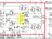
The schematic section - this is the output of the left channel power amp board (right channel identical). The caps in question hi-lighted yellow. The negative side of both are connected to the higher voltage potential:
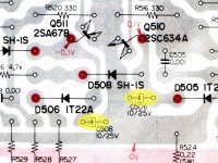
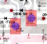
The PCB component layout for the same 2 caps:
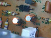
The right channel had the caps installed according to both schematic & silkscreen:
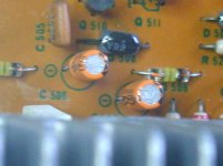
The left channel though, were reversed. It worked fine this way for 40 years!
Clearly one way is incorrect, but which way is really correct?
However, the schematic has always bothered me a bit, showing 2 pairs of caps being used in what appears to be the wrong polarity (at least to my limited understanding of all the finer details of electronic design).
I'm hoping an expert can comment on the circuit, and tell me if the schematic is correct or not. And if it is correct, why the caps are connected in seemingly reverse polarity given the voltages noted on the schematic?
The schematic section - this is the output of the left channel power amp board (right channel identical). The caps in question hi-lighted yellow. The negative side of both are connected to the higher voltage potential:

The PCB component layout for the same 2 caps:

The right channel had the caps installed according to both schematic & silkscreen:

The left channel though, were reversed. It worked fine this way for 40 years!

Clearly one way is incorrect, but which way is really correct?
Well most of the time they only had a fraction of a volt, probably not enough to depolarize Al2O3
They are to set the time constant for SOA protection and not particularly problematic if they
fail open. If fail closed then the protection will no longer be working
They are to set the time constant for SOA protection and not particularly problematic if they
fail open. If fail closed then the protection will no longer be working
Thank you Mark!Well most of the time they only had a fraction of a volt, probably not enough to depolarize Al2O3
They are to set the time constant for SOA protection and not particularly problematic if they fail open. If fail closed then the protection will no longer be working
I knew the small reverse bias was not a concern, but the totality of circuit function escaped me.
Do you think the schematic orientation is correct? Or, would a film cap serve better in this use?
The caps should be installed with the positive terminal up, as you would reasonably expect. It worked fine for 40 years because there is essentially no voltage on there at all and they used some of the orange low leakage Elnas to boot (which in general are exceptionally reliable - leakage and degradation of the oxide layer under a short circuit condition are two sides of the same coin).
You may have difficulty fitting any sort of film cap there, besides it rather seems like a waste. Low leakage electrolytic really seems like the best choice here. There is about one series left that you can actually buy.
It would be interesting to see what the old caps measure like in terms of ESR and leakage. If ESR isn't unusually high and leakage comes back into spec with some minimal reforming, these may well be good to go for the next couple decades, crazy as it sounds.
The original Orange cap were Xicons. I suspected the color indicated low-leakage, so replaced them with Nichicon KL low-leakage.The caps should be installed with the positive terminal up, as you would reasonably expect. It worked fine for 40 years because there is essentially no voltage on there at all and they used some of the orange low leakage Elnas to boot (which in general are exceptionally reliable - leakage and degradation of the oxide layer under a short circuit condition are two sides of the same coin).
Well, I can either leave the replacements in-place (reversed) and hope nothing goes wrong, or take it apart to unsolder & flip the caps around. If going to that trouble, might as well replace with films. Unless ESR is a consideration?You may have difficulty fitting any sort of film cap there, besides it rather seems like a waste. Low leakage electrolytic really seems like the best choice here. There is about one series left that you can actually buy.
Wima MKS2 do just fit. Won't sit flush to the board, but neither did the original Xicons.
Don't have hi quality measuring tools, just one of the cheap chinese T7 things that abound everywhere for @ $20-25. Only use it for close value matching, but FWIW here's what it reports, lowest to highest of the 4 caps:It would be interesting to see what the old caps measure like in terms of ESR and leakage. If ESR isn't unusually high and leakage comes back into spec with some minimal reforming, these may well be good to go for the next couple decades, crazy as it sounds.
Capacitance: 10.15 - 10.33 uF
"Vloss": 1.4 - 1.6%
ESR: 2.1 - 2.4 ohms
I have no idea how to interpret "Vloss", or if the ESR is appropriate for this size cap.
Thanks for your help!