Hi there.
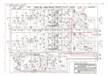
Got dead n88 from a friend. PSU is not oscillating, i.e. "starter" circuit is not firing the sawtooth. While voltage regulator checked fine - there's a good stable output at the L401 choke, adjustable with trimmer pot, the next circuit seems not working. Both Q407 and Q408 are good, small caps are good, resistors are in their nominal values. No heat, no signs of burn. On power on it has 110v on r414 upper leg (adjustable) and 0,68V on r414 lower leg irrelvant to any adjustments and input voltage. So both q407 and q408 shows fully opened, constantly. Any thoughts? (check attachment pic). Also don't understand why there's -5V on q407 collector, where shall it came from?

Got dead n88 from a friend. PSU is not oscillating, i.e. "starter" circuit is not firing the sawtooth. While voltage regulator checked fine - there's a good stable output at the L401 choke, adjustable with trimmer pot, the next circuit seems not working. Both Q407 and Q408 are good, small caps are good, resistors are in their nominal values. No heat, no signs of burn. On power on it has 110v on r414 upper leg (adjustable) and 0,68V on r414 lower leg irrelvant to any adjustments and input voltage. So both q407 and q408 shows fully opened, constantly. Any thoughts? (check attachment pic). Also don't understand why there's -5V on q407 collector, where shall it came from?
-5v comes from the feedback winding rectified by D406/7.
If there is -5v at that point, look with your oscilloscope at the wave form.
If there is -5v at that point, look with your oscilloscope at the wave form.
Thanks. It's zero there as well. I mean , the lower leg at r414 just 0,68v. Thats because of both q407/8 are open, so anywhere in between is just about zero.
Q406 is good at all legs. That's a DIP6 dual BJT. I can confirm that regulator is working just fine - L401 choke is showing stable regulated 110V adjustable by the pot, which means Q406 and zeners and all input circuitry works just fine.
What I can not understand is how "Starter" circutit is operating. What I see from schematic is:
1. on power on Q408 turns on by R414-R-416-R417 voltage divider
2. then Q408 turns on Q407 feeding some current to Q407 base through R412 and Q408 C-E
that's where I am stuck. I understand Q408 shall throw some voltage to "starting" winding (pins 8 and 9) through D406 and D407. That shall fire up Q409-Q412 inverter. Inverter shall do single switch at "Main" transformer winding (pins 1 and 2), which shall induce power in "Feedback" winding (pins 3 and 4). This throws -5V back to Q408 base turning it off and all thing starts over again (switching continues).
What makes me stuck is that current via R414 is just 110V/68kohms = 1.6ma. It shall be never enough to induce the impulse in starting winding as there's just 6-7 turns of wire with literally zero copper resistance to ground. How the starting winding shall start, I dont understand.
It does cause a small magnetic field. Maybe that's enough to get going?
Jan
how to get it measured? The problem is there's no oscillation while I can not find any faulty parts. Magnetic field shall be induced with some voltage and current. But there's nothing on the pins, also checked with digital scope just to be sure nothing pops on power-on.
Check R402 (fuse resistor), before L401 you should have voltages according your version of voltage (is it US or EU model).
If there is no voltage on that point you will not have oscilation (current through the T403 will not trigger T401).
If there is no voltage on that point you will not have oscilation (current through the T403 will not trigger T401).
- Home
- Amplifiers
- Class D
- sony ta-n88 dead psu repair