Hi Mooly,
Sounds like a good plan, getting the power amps working first.
I will do some testing, the driver transistors, resistors and so on.
The problem is, I don't have any conventional supply.
Is there a better substitute for the output devices than the ON Semi MJ21193 & MJ21194?
In the meantime I did test all resistors and remaining transistors on the PSU board, all is working fine, even the 0.22Ω, the only failure is Q611.
Knowing that now, I would guess the output blew first, overloaded/shorted the PSU and killed Q611, just funny the thermal fuse still works...
I'm very puzzled about the very low hfe on all the original 2023's.
I tried measure them whit a cheap DMM, they are around 7, still very low, and well below 30 as specs say.
The new ones from Dönberg measure from 25 to 67 on the same DMM.
Wonder if the originals was stressed, then again what are the odds they all(including the two in the reg.) end up whit allmost the same hfe?
If Johnm or anyone else have keept the replaced original working 2023's it would be interesting to know the hfe.
Maybe testing the regulator part, as you explained way back in this thread, would show if the 2023's truely are working or not?
I think the onsemi parts would probably be as good as any tbh. If you are doubtful on the hfe then it might be worth rigging a small test circuit up. 9 volt battery etc and measure Ib and Ic and try and get some idea that way. The hfe shouldn't alter if the devices were stressed but still functional. Back in those days high voltage high gain devices were pretty rare.
Ok, I'll order those onsemi's when I have tested the rest of the power amp (in case I need more spares).
I tested the PSU (no switching transistors fitted), using the original 2023's in the regulator, a bulb as load, I can set voltage over bulb/C613 from 170-270V.
So the regulator is working fine, (service manual specify 250V over C613)
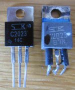
I'm a but unsure on the new 2023's they look a little "made in china" not fake, but not quite "right"
I'd be very interested to hear your opinion.
Just found this post by John http://www.diyaudio.com/forums/solid-state/181121-sony-ta-f6b-psu-repair-37.html#post2463827 he measure a 2023R to 009, not that far from mine, 007, I'll put that down to diffrence in measuring current.
And the new ones John got form Dönberg measure a lot higher, like mine.
So I guess that clear up things a bit 🙂
It's like you say: "Back in those days high voltage high gain devices were pretty rare."
So I take it high gain is not needed (or maybe even wanted?) in this PSU?
I tested the PSU (no switching transistors fitted), using the original 2023's in the regulator, a bulb as load, I can set voltage over bulb/C613 from 170-270V.
So the regulator is working fine, (service manual specify 250V over C613)
I'm a but unsure on the new 2023's they look a little "made in china" not fake, but not quite "right"
I'd be very interested to hear your opinion.
Just found this post by John http://www.diyaudio.com/forums/solid-state/181121-sony-ta-f6b-psu-repair-37.html#post2463827 he measure a 2023R to 009, not that far from mine, 007, I'll put that down to diffrence in measuring current.
And the new ones John got form Dönberg measure a lot higher, like mine.
So I guess that clear up things a bit 🙂
It's like you say: "Back in those days high voltage high gain devices were pretty rare."
So I take it high gain is not needed (or maybe even wanted?) in this PSU?
Attachments
The two transistors in the reg are in parallel with no current sharing resistors to equalise any imbalance and so that means they should be closely matched so that they share the current equally. Aside from that and I would say the regulator is the least "critical" part of the PSU with regard to actual device characteristics. Its the switching section where it becomes more critical.
I wouldn't like to say if they were fake or not. The gap between the S and K looks a bit elongated but I wouldn't like to call on that alone.
I wouldn't like to say if they were fake or not. The gap between the S and K looks a bit elongated but I wouldn't like to call on that alone.
Ok, I think the best bet is to use the new matched 2023's in the regulator, and replace the one bad in the switching section whit one from the regulator, they are all "R" grade and a very close match.
I can't help having a bad feeling about those new 2023's...
For the power amp, I've found a old lab supply, but it only goes up to 2x30V/1or2A, and I'm not sure if it possible to make +30V 0V -30V from the 3x30V, and maybe 30V is too low.
I can't help having a bad feeling about those new 2023's...
For the power amp, I've found a old lab supply, but it only goes up to 2x30V/1or2A, and I'm not sure if it possible to make +30V 0V -30V from the 3x30V, and maybe 30V is too low.
That sounds like a plan 🙂
30-0-30 should allow the amps to operate I would have thought. Haven't got the circuit in front of me but as long as the front end CX167 (was it ?) has sufficient supply then it should all work.
Without knowing the PSU's you have its hard to say but as long as you can cobble together a 60 volt supply with a centre tap it should be fine. If the grounding permits you can connect two 30 volt supplies in series and take the 0 from the "middle" but be aware that it might not work if the PSU mains ground is connected to the PSU 0 volt output. And beware any ground connection created via test equipment mains leads etc.
I'll give it a go when I get the supply home.
The front end is CX171.
By the way, the output transistors, do they need to be matched too, or just same markings?
The front end is CX171.
By the way, the output transistors, do they need to be matched too, or just same markings?
Good, so I only need to order 4 🙂
Another thing, when I search mouser.com for 2023 it came to whit a replacement NTE394, which is quote: " Cross Reference Match For: 18540806 2SC2023 2SC2809 2SC2900"
Datasheet http://www.mouser.com/ds/2/300/nte394-85957.pdf
Might be a solution if those 2023's I got turn out to be fake, which I got a bad felling they are 🙁
I hooked the lab supply up to the power amp (SMPS disconnected, blown output transistors removed from one channel)
The soft start relay clicked, that's about it, no sound, no click from the speaker relay, no light in the meters, not even glowing.
Current draw was about 200mA on the + rail, 100mA on the - rail, that's to be expected as the relay and meter light are on the + rail.
I guess 30 V just isn't enough, or maybe removing the output transistors from one channel prevent the speaker relay from activate?
I do have another supply from an active speaker, but its too high, 55-0-55V, maybe a 100W bulb on the AC side will bring it down a bit.
Jan, I'm travelling at the moment and so it will probably get into next week before I can take a closer look. Even though the speaker relay doesn't pull in there should be zero volts DC off set at the output transistors. You can deduce output transistor current from any volt drop across the emitter resistors. Should be low. If the offset is high then ensure the CX chip has enough supply.
Hi Mooly, thanks for all your help so far 🙂
The active speaker supply whit a 100 W bulb on the AC line is now down to 51-0-51 V, and will probably drop below 49 V when connected to the Sony amp.
I'll try hook it up, and get those readings.
In the meanwhile I did some reading here on diyAudio and found these 2 posts by Johnm
http://www.diyaudio.com/forums/solid-state/220179-faulty-sony-ta-f6b.html#post3175922
and http://www.diyaudio.com/forums/solid-state/220179-faulty-sony-ta-f6b-2.html#post3178125
They makes me 1) worried that those new 2023's are either fake or 2) the "R" rating is a very low hFE, both Johns and mine surviving 2023R's measure about 7-10.
ON Semi suggested BUX85G as a substitute for 2023
https://www.onsemi.com/PowerSolutio...=EE&category=EE6&question=4680&includedC=true
Using the active speaker supply, rails drops to 41 V, the 100W bulb glows slightly, softstart relay clicks, speaker relay doesn't, volt drop across emitter resistor is 10mV.
Wonder why the meter light doesn't even glow, they (or at least one of them) must be OK, as the softstart relay clicks.
I hope you are enjoying your trip 🙂
Wonder why the meter light doesn't even glow, they (or at least one of them) must be OK, as the softstart relay clicks.
I hope you are enjoying your trip 🙂
Thanks Jan. Without access to diagrams I can't add much at the moment but it sounds OK in the sense the outputs sound to be drawing around the correct current. DC voltage going into the relay (speaker side) should be zero. Seem to remember the bulbs are resistively fed but its simple circuit... doesn't sound anything drastically wrong up to now though.
I know you don't have access to the diagram right now, I just wanted to post a update, while fresh in my memory 🙂
I tested all transistors on the power amp board.
All transistors was removed from the board when tested.
They was all OK, except Q354 (C1364), the tester did read OK, but the buzzer sounded diffrend, and the hFE was way too high, over 6000, all the other C1364's was around 100-120.
Ileak was over 6000 too, was 0 on all the other C1364's.
Q354 is in the same (right) channel as the two blown output transistors.
I used Q402 from the thermal detect circuit to replace it, to keep both channels the same.
I bought a damaged Sony TA-N86B a while back, these use a similar supply the the TA-F6B, the main difference is the the section with the relay is populated.
I hoped for an untouched unit with a fairly minor fault, but got the opposite, it had suffered a major meltdown and someone had made a half-hearted, clumsy attempt to fix it. Half of the 2SC2023s had blown, two of the switching ones and one of the regulator ones. The 2SA911 had also blown, that was fun to replace. The were also quite a few blown resistors, and a few of the capacitors looked heat damaged.
I've replaced all of the electrolytic capacitors, most of the film capacitors, the 2SA911, all of the 2SC2023s with FSC2335s, and I'm almost finished replacing all of the resistors.
I'm getting close to testing the power supply, how did you guys go about starting yours? Normally I would slowly increase the mains supply using a variac, but I know many SMPSs don't like this. On the other hand, the TA-N86B's supply isn't anything like most SMPSs, hence why I'm a little puzzled.
Hi amc184,
If I remember correctly from far back in this thread, a 100W light bulb in series whit the mains to limit the current, and a small bulb as load, is what Johnm used.
I used the bulbs to test the regulator part of the PSU, it worked fine, but I'm not sure what to fit in the switching section, so I hope you will give us update when you tested yours 🙂
Have you tested the power amp section?
I've got a bulb tester, so I'll use that when I test the supply. I just hate the idea of chucking full mains voltage straight at something like this, but I guess the light bulb will save me from the biggest bangs.
I haven't tested the power amp section yet, I'm not really sure if it will work. For that section I do want to be able to use a variac, so I've built a linear supply.
I haven't tested the power amp section yet, I'm not really sure if it will work. For that section I do want to be able to use a variac, so I've built a linear supply.
Hi Mooly 🙂
I replaced Q402 (C1364) whit a C2235 and fitted the new output transistors (MJ21193/4)
Tried to power it up on the linear supply, idle current is about 7.5mV in both channels, no click from the speaker relay, only the softstart relay clicks.
Rail's drop to about 40-0-40V, 100W light bulb on mains glows slightly.
The meter light still don't light, not even glowing, weird since the softstart relay is grounded through the meter light.
Just did a check on the DC (collector on the output's and ground) 74mV R ch. and 4.5mV L ch.
R405 is OK.
Last edited:
- Home
- Amplifiers
- Solid State
- Sony TA-F6B PSU repair