The 48 volts is OK
The reading on the opamps indicates a problem in that area. As this stage is AC coupled then the problem has to be local to that area. All these voltages are measured with respect to ground.
Confirm the supplies to the opamp are OK at -/+15 volts on pins 4 and 8 of the opamps.
In post 31 you mentioned R211 and 261 burning. Did you find a reason for that ?
The voltage from the junction of R377 and R378 to ground should be zero volts. If it is not then this indicates another separate issue in the power amp section.
readings on 4 and 8 are low 2.8v and 1.7 volts,couldnt find anything else wrong after changing the burnt resistors,you did mentioned that the attenuator may be at fault also.
Pins 4 and 8 are the first problem then... supplies missing.
Trace back to the voltage regulators in the PSU and look for open circuit resistors. Check the voltages on Q604 and 606
Trace back to the voltage regulators in the PSU and look for open circuit resistors. Check the voltages on Q604 and 606
Pins 4 and 8 are the first problem then... supplies missing.
Trace back to the voltage regulators in the PSU and look for open circuit resistors. Check the voltages on Q604 and 606
Q606 13.4 v 35.4 12.7v
Q604 13.5v 35.5 12.3v
will have a closer look lata at the psu for open circuit
Q606 13.4 v 35.4 12.7v
Q604 13.5v 35.5 12.3v
will have a closer look lata at the psu for open circuit
well ive looked for hours,cant find no burns anywhere,loose connections😕
Taking this one step at a time lets see how much current is being drawn from the regulators. That will help tell us whether the fault is really a PSU one or not. We can deduce that from accurate voltage readings so can you measure the voltage across R601 and across R609
Also do any one of the op amps feel warmer than the others.
Also do any one of the op amps feel warmer than the others.
Taking this one step at a time lets see how much current is being drawn from the regulators. That will help tell us whether the fault is really a PSU one or not. We can deduce that from accurate voltage readings so can you measure the voltage across R601 and across R609
Also do any one of the op amps feel warmer than the others.
r609 reads 9.8v
r601 reads 6.2v
opamps ic 251 warm to touch others are cold
It might be worth removing IC251 to see if it's drawing excess current. See if the voltages come up with it out.
It might be worth removing IC251 to see if it's drawing excess current. See if the voltages come up with it out.
have removed ic251,didnt come out easy,need a new one now.
ic 201 pins 1 and 5 read 0v and pins 8 and 5 now read 15.1v
Seems like the IC is zapped.
Be sure on your voltage readings. Pin 8 is positive supply and pin 4 is negative supply.
Be sure on your voltage readings. Pin 8 is positive supply and pin 4 is negative supply.
Seems like the IC is zapped.
Be sure on your voltage readings. Pin 8 is positive supply and pin 4 is negative supply.
will get some from rs in the week
Might also be worth getting some "cooking grade" opamps too, and fit these until you are sure its all OK. Maybe fit sockets ? The cheap TLO72 dual opamp would be fine.
Something has definitely happened for the opamp to fail like this. I would really suggest you check the PCB very carefully for any solder splashes. The only thing that would kill the IC is overvoltage (applied to any pin) or a reversed supply. Shorting pins out on a working opamp although not recommended won't actually harm it 99.99999% of the time.
Have you tried solder braid for removing parts. The opamps would come out in seconds and still look as good as new... leaving the PCB totally unharmed.
Worth checking the power amps are functioning OK before ordering parts.
If you look at the circuit, if IC201 and 251 were removed (or isolated) and pins 1 and 5 in one channel and pins 3 and 7 in the other were linked then the amp should work.
ok i will try that,i do have a couple of spare TL072'S,never tryed solder braid.will let you know how it goes,will have another look tomorrow.many thanks.Might also be worth getting some "cooking grade" opamps too, and fit these until you are sure its all OK. Maybe fit sockets ? The cheap TLO72 dual opamp would be fine.
Something has definitely happened for the opamp to fail like this. I would really suggest you check the PCB very carefully for any solder splashes. The only thing that would kill the IC is overvoltage (applied to any pin) or a reversed supply. Shorting pins out on a working opamp although not recommended won't actually harm it 99.99999% of the time.
Have you tried solder braid for removing parts. The opamps would come out in seconds and still look as good as new... leaving the PCB totally unharmed.
Worth checking the power amps are functioning OK before ordering parts.
If you look at the circuit, if IC201 and 251 were removed (or isolated) and pins 1 and 5 in one channel and pins 3 and 7 in the other were linked then the amp should work.
well all is not well,when you turn it on the red light on volume knob stays red,does not change to green,and pcb is not good where ic251 goes,pin 7is in poor condition,the solder will not take there.im about at the end of my patients now...i dont normally give in,but im close.
Last edited:
The red light is a sign that there is a problem with the power amp stages too (probably a high DC offset).
Measure from ground to the output of each power amp (measure before the speaker relay). It should be zero volts on each channel.
The IC and this problem are all unrelated.
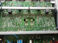
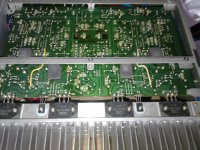
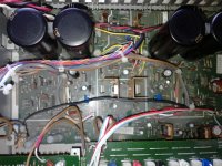
Maybe post some detailed (and they would have to be detailed) shots of the PCB print side to see if we can spot any problems.
Measure from ground to the output of each power amp (measure before the speaker relay). It should be zero volts on each channel.
The IC and this problem are all unrelated.
Maybe post some detailed (and they would have to be detailed) shots of the PCB print side to see if we can spot any problems.
The red light is a sign that there is a problem with the power amp stages too (probably a high DC offset).
Measure from ground to the output of each power amp (measure before the speaker relay). It should be zero volts on each channel.
The IC and this problem are all unrelated.
Maybe post some detailed (and they would have to be detailed) shots of the PCB print side to see if we can spot any problems.
will take a picture,but of what you say is all straight over my head mooly😕
is it worth me continuing,the v.i board is now knackered,with the solder not taking.
Hmmm...
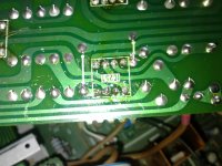
If you look at your first picture showing IC251 there is what appears to be a solder splash across the print (top right pin of IC251). What I wonder is whether a bit of solder like that has fallen onto the board somewhere and has caused a short doing the damage.
You are going to have to get the technique of neat soldering (and desoldering) nailed to have any real hope of fixing this. The PCB around IC 251 isn't that bad.
It's up to you whether you feel it worthwhile as a learning exercise to continue.
With solder braid that IC will come out in seconds and then the print can be cleaned and prepared/repaired. I suspect that is the least of the problem though.
The point I mean on the circuit to measure is the junction of R327 and 328 for one channel and R377 and 378 on the other. You measure from ground to those points on DC volts.
Hmmm...
If you look at your first picture showing IC251 there is what appears to be a solder splash across the print (top right pin of IC251). What I wonder is whether a bit of solder like that has fallen onto the board somewhere and has caused a short doing the damage.
You are going to have to get the technique of neat soldering (and desoldering) nailed to have any real hope of fixing this. The PCB around IC 251 isn't that bad.
It's up to you whether you feel it worthwhile as a learning exercise to continue.
With solder braid that IC will come out in seconds and then the print can be cleaned and prepared/repaired. I suspect that is the least of the problem though.
The point I mean on the circuit to measure is the junction of R327 and 328 for one channel and R377 and 378 on the other. You measure from ground to those points on DC volts.
dc volts between r327 -328 is -13.41v
and on r377-378 is -.21
-13 volts is no good. Certainly a problem on that channel.
Is the other reading -0.21 volts ? If so that could be OK. Although it should be as near zero as possible it may not be due to a fault.
It's up to you what you want to do of course...
It really involves powering the amp via a bulb limiter (100 watt bulb in series with the mains) to limit current and making a several detailed voltage measurements and resistance checks. The bulb can prevent damage in the event of the output transitors drawing too much current.
Power amp faults tend to be short circuit output transistors, probably failed driver transistors (collateral damage) and failed low value resistors like those 0.1 ohms.
- Status
- Not open for further replies.
- Home
- Amplifiers
- Solid State
- sony ta-f444es tweeks


![P311011_12.15_[01].jpg P311011_12.15_[01].jpg](https://www.diyaudio.com/community/data/attachments/230/230875-1ebc358d6676d03ac43776c1e23bebf6.jpg?hash=Hrw1jWZ20D)

![P311011_12.17_[01].jpg P311011_12.17_[01].jpg](https://www.diyaudio.com/community/data/attachments/230/230914-152544d795654486ef5c7b1390140c73.jpg?hash=FSVE15VlRI)
![P311011_12.17_[02].jpg P311011_12.17_[02].jpg](https://www.diyaudio.com/community/data/attachments/230/230949-acb2c6f84a7b96c0fe1379911dd455d6.jpg?hash=rLLG-Ep7ls)