finerly found schematics for this sony ta-f444es,can it be tweeked in any way,i.e caps transistors ,transformer etc etc.


Too blurry to make out... what are the opamps in the next to last pic ? Looks to be a servo wrapped around two opamps in the signal path.
Too blurry to make out... what are the opamps in the next to last pic ? Looks to be a servo wrapped around two opamps in the signal path.
they are bad pictures arent they,will try and improve them.op amps are
TL082P AND NE5532P
hope that helps.?? P011011_13.27.jpg thats about as good as i can get it mooley.
Attachments
Last edited:
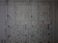
this is the best i can get the schematic pics,see what you think.
thanks for looking


![P011011_13.36_[01].jpg](https://www.diyaudio.com/community/data/attachments/241/241227-4c70c913e585568723e43c61b6dcace5.jpg?hash=THDJE-WFVo "P011011_13.36_[01].jpg")
![P011011_13.36_[02].jpg](https://www.diyaudio.com/community/data/attachments/241/241250-cbc72b9a2f1612e80326cb5a8bedec24.jpg?hash=y8crmi8WEu "P011011_13.36_[02].jpg")

![P011011_13.37_[01].jpg](https://www.diyaudio.com/community/data/attachments/241/241285-3ce863c9497d30c9e356e54e4d20173f.jpg?hash=POhjyUl9MM "P011011_13.37_[01].jpg")


thanks for looking
Last edited:
If it's older than 20 years, renew all the electrolytic capacitors. Look for electrolytics in the signal path and see if you can substitute Wima MKS2 series polyesters in their place.
Opamps - nothing wrong with the NE5532's, leave them be. You'd likely have to mess around improving local decoupling if you were to change them, anyway.
Overall, a well built amp by Sony. If I had one criticism, it's the tone control in the power amp's feedback path - i've never liked this method, but it was commonly done on amps of this era.
Thanks for the rescan... it's a bit of a quirky design in parts.
Good advice from Jaycee on the caps etc but I'm going to suggest you look at those opamps.
It's an odd arrangement... the overall phase of the two opamps gives a 180 degree phase reversal so that is obviously for political correctness in maintaining non inverting of phase for the amp as a whole. The DC servo is needed as the last opamp feeds the "attenuator" control (is that the balance control ?) and so any DC at all would result noisy operation as the pot is turned.
The TL082 is perfect for use as a DC servo but the 5532 I think could be bettered here maybe with some other small tweaks...
If you are interested I'll give it some thought because it's quite an unusual arrangement and, while many opamps would work straight off it would be good to optimise it.
Thanks for the rescan... it's a bit of a quirky design in parts.
Good advice from Jaycee on the caps etc but I'm going to suggest you look at those opamps.
It's an odd arrangement... the overall phase of the two opamps gives a 180 degree phase reversal so that is obviously for political correctness in maintaining non inverting of phase for the amp as a whole. The DC servo is needed as the last opamp feeds the "attenuator" control (is that the balance control ?) and so any DC at all would result noisy operation as the pot is turned.
The TL082 is perfect for use as a DC servo but the 5532 I think could be bettered here maybe with some other small tweaks...
If you are interested I'll give it some thought because it's quite an unusual arrangement and, while many opamps would work straight off it would be good to optimise it.
yes please open to any ideas,also,the bias pots could do with upgrading,could you recommend better pots,i have a friend who has a ta-f777es,now that is a class amp,i'd like to get it to perform as close to that,if possible.
I'll have a think on the opamp stage...
Pots... it's either a case of finding new that are physically the same, going multiturn and drilling the board so they fit properly (nothing worse than ill fitting parts with bits of wire 🙂) or, fit a multiturn temporarily and adjust and when totally happy with the result remove and replace with fixed resistor network.
Pots... it's either a case of finding new that are physically the same, going multiturn and drilling the board so they fit properly (nothing worse than ill fitting parts with bits of wire 🙂) or, fit a multiturn temporarily and adjust and when totally happy with the result remove and replace with fixed resistor network.
This opamp stage isn't quite so obvious in its operation as you might think... that's why I wanted to think it through. More than that I actually breadboarded it to investigate.
Easy bit first... the TL082.
As I mentioned a FET opamp like this is perfect for a DC servo but two thoughts came to mind. I'm puzzled (well down to cost I suppose) why the better specified TL072 isn't used. It has a lower noise... does that matter... well in theory it does feed directly into the first audio opamp stage. Absolutely nothing lost in swapping it if you wish although in practice it may be a half of a quarter of nothing as far as total noise is concerned.
The 330 ohm on the servo non inverting input to ground is a curiosity. It serves no purpose to the operation of the circuit as the FET opamp inputs have currents measured in the femto amp range. Maybe the machine that populated the PCB "didn't do wire links" 🙂
The NE5532...
You have choices. The LM4562 is the successor to the 5532 (one I haven't used) and has a good reputation.
The OPA2604 is one I have used and would definitely try as it does seem to have a "unique" sound quality (musical in the best sense of the word).
The other to try is the OPA2134.
So maybe fit sockets for the 5532 replacement and listen for yourself.
I'll have a think on the opamp stage...
Pots... it's either a case of finding new that are physically the same, going multiturn and drilling the board so they fit properly (nothing worse than ill fitting parts with bits of wire 🙂) or, fit a multiturn temporarily and adjust and when totally happy with the result remove and replace with fixed resistor network.
me again,having trouble with finding out what pots i need,nothing writen on the old ones,and when i use the multi meter ,the readings are all over the place,how else to find the right pot for the job.😕
Hi Paul,
Very blurry on the circuit but it looks like 470 meaning 470 ohm which sounds right anyway.
You must be careful and start with the bias on minimum if you replace the pots. That means having the preset initially on max resistance (470 ohm) so that the transistor it operates on (the vbe multiplier) is fully on giving lowest bias current.
Edit... you can not measure resistances accurately in circuit... remove the pot to measure.
Hi Paul,
Very blurry on the circuit but it looks like 470 meaning 470 ohm which sounds right anyway.
You must be careful and start with the bias on minimum if you replace the pots. That means having the preset initially on max resistance (470 ohm) so that the transistor it operates on (the vbe multiplier) is fully on giving lowest bias current.
Edit... you can not measure resistances accurately in circuit... remove the pot to measure.
thanks mooly,be nice to find multi turn pots,but,not having much luck sourcing them in those values,any ideas?
Try these,
VISHAY SPECTROL|64W-501..|TRIMMER, 64W 25-TURN 500R | CPC
Others available,
Your Search Results | CPC
thanks mooly,will let you know how it sounds.once all the parts arrive.
OK...
Just be careful with the initial pot setting. Get it the wrong way and it could spell disaster on switch on.
Just be careful with the initial pot setting. Get it the wrong way and it could spell disaster on switch on.
OK...
Just be careful with the initial pot setting. Get it the wrong way and it could spell disaster on switch on.
yes will do,well i replaced the TL082 with the TL702 this morning,not sure if that made inprovement or not,but then i replaced the NE5532 with the OPA2134's,and massive improvement,well pleased,next is the replacement elecs in the signal path for some wima's

That's good...
The TL082 is used as a DC servo and so it's only possible contribution is noise as it biases the stage directly. The TL072 is slightly better specified noise wise than the 82. It won't alter the audio as such.
The OPA2134 is an excellent performer... as you have found out.
The TL082 is used as a DC servo and so it's only possible contribution is noise as it biases the stage directly. The TL072 is slightly better specified noise wise than the 82. It won't alter the audio as such.
The OPA2134 is an excellent performer... as you have found out.
If it's older than 20 years, renew all the electrolytic capacitors. Look for electrolytics in the signal path and see if you can substitute Wima MKS2 series polyesters in their place.
Opamps - nothing wrong with the NE5532's, leave them be. You'd likely have to mess around improving local decoupling if you were to change them, anyway.
Overall, a well built amp by Sony. If I had one criticism, it's the tone control in the power amp's feedback path - i've never liked this method, but it was commonly done on amps of this era.
i make that c307 and c357 to replace wima's,is that right😱
Are they 47uF ? A film cap would be physically massive (a bit overkill 🙂)
These are fine,
PANASONIC|ECA1CAM470X|CAPACITOR, 47UF 16V | CPC
These are fine,
PANASONIC|ECA1CAM470X|CAPACITOR, 47UF 16V | CPC
- Status
- Not open for further replies.
- Home
- Amplifiers
- Solid State
- sony ta-f444es tweeks