It seems an intermittent fault, which has now gone away when probing for voltages, maybe a damaged solder joint of which I'll refresh all in the area.You mentioned voltage on R401 to be off. Well when output 1 is used things float in the air at that side so it must be at the input.
Maybe I misunderstood so I am out of the thread. Good luck!
I'll have a closer look but I don't think the to-92 case style were affected?Sony loved those 2SC458 transistors which are known to fail. The odd thing is they measure fine on a DC test but stop passing audio. You can tell them as the legs go black. I recently refurbished a Sony reel to reel, low level one channel nothing on the other. Replacing the 458s brought it back to spec.
I thought that only the "outhouse" type 458 had the problem. Very curious as to where the -V is coming from, maybe pull the relay to see if it disappears.
Its gone now, hopefully intermittent, but going to give the board a good clean and resolder see how it goes.
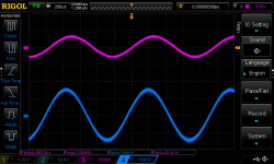
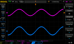
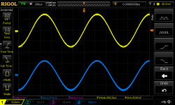
Back to the original fault, I've check the volume pot and swapped over the 2sk58's and it's still on the right channel, only seems to happen when the pot is set to around 170mv into the circuit, the left channel stays 170mv input to the flat amp the right drops to 50mv into the flat amp.
Back to the original fault, I've check the volume pot and swapped over the 2sk58's and it's still on the right channel, only seems to happen when the pot is set to around 170mv into the circuit, the left channel stays 170mv input to the flat amp the right drops to 50mv into the flat amp.
Do you have a scope? If you do monitor the wiper of the volume pot to see what's going on there.
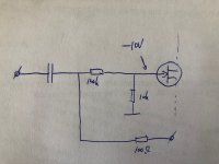
Intrigued by the first schematic in post #16 I keep looking and there is no other way of getting DC at the gate of the 2SK42 as there is nothing else connected except C310 which was replaced for a film cap if I am not mistaking... It must be my poor reading skills or otherwise I don't see it. There is an attenuation network there and no other DC possibility than the JFET. The output is dangling in the air so no DC from there and R326 is out of the equation as well.
Or is a device connected to output "one" that causes DC offset at that point?!
Or is a device connected to output "one" that causes DC offset at that point?!
Last edited:
Intrigued by the first schematic in post #16 I keep looking and there is no other way of getting DC at the gate of the 2SK42 as there is nothing else connected except C310 which was replaced for a film cap if I am not mistaking... It must be my poor reading skills or otherwise I don't see it. There is an attenuation network there and no other DC possibility than the JFET. The output is dangling in the air so no DC from there and R326 is out of the equation as well.
Or is a device connected to output "one" that causes DC offset at that point?!
I cannot see why either but it was there confirmed by my fluke meter numerous times, as stated started probing voltages around outputs and relay drive and it rectified itself, errant solder ball small cut piece of component lead, could be the jfet? I'm not sure but glad it's rectified hopefully permanently
As pointed out in normal circumstances (clean PCB, no debri etc) it can almost only be the JFET and/or the cap but that one was replaced.
"Hopefully" will not solve a defective JFET and "rectified itself" only exists in fairy tales, sorry. Again, are you sure the connected device is not causing this or is there no device connected when this happens?
Could it be that an RF source is nearby?
"Hopefully" will not solve a defective JFET and "rectified itself" only exists in fairy tales, sorry. Again, are you sure the connected device is not causing this or is there no device connected when this happens?
Could it be that an RF source is nearby?
Last edited:
Something similar like that happened to me once. Turned out I had the meter neg lead not on ground but on a supply point. Of course I measured some DC where it shouldn't be.
Rectified itself too (i.e. I smarted up).
Just saying.
Jan
Rectified itself too (i.e. I smarted up).
Just saying.
Jan
Jan, in this case there is a problem as described in the first post and more specifically in post #16 and OP has measured numerous times. Correcting ones own mistakes is called "rectified itself"? I sure wish I had more of those issues that rectify themselves 🙂
Very much the TO92 style. I have the suspects blu tacked to my workshop wall as reminders.I'll have a closer look but I don't think the to-92 case style were affected?
All I can say is the 10v was there, now not. You are probably correct and the jfet is defective. So I can test is there a recommended circuit?Jan, in this case there is a problem as described in the first post and more specifically in post #16 and OP has measured numerous times. Correcting ones own mistakes is called "rectified itself"? I sure wish I had more of those issues that rectify themselves 🙂
Again, my eyes see this circuit. Unless the capacitor identifies as a resistor (which is of course fully accepted these days) then it can only be the JFET... Please correct me if I am wrong! Debate and anecdotes are nice distractions but this is IMO the bare case.
BTW you mentioned -10V not 10V. That is only 20V difference 🙂 Volt is with a capital V as well. If we can't even write stuff correctly solving issues certainly will be too difficult.
BTW you mentioned -10V not 10V. That is only 20V difference 🙂 Volt is with a capital V as well. If we can't even write stuff correctly solving issues certainly will be too difficult.
Attachments
Last edited:
Volt is with a capital V as well. If we can't even write stuff correctly solving issues certainly will be too difficult.
Don't think there is a need for the tone in this part of the reply!
Ok so original fault turns out to be the volume control when at the set level on the first pic one channel jumps 2x what the other channel is and out if phase, turn it slightly up and it normalises, this is with the volume control separate to the amp.
Attachments
So it is not the circuit as discussed in post #16??! That -10V is OK? The schematic says "0V".
I get the idea we are having 2 issues here. Strong moving target feeling in this one, padawan.
I get the idea we are having 2 issues here. Strong moving target feeling in this one, padawan.
The original fault in post one was one channel seeming to loose volume and what I can only describe as low end when the volume control was set at a certain point, after taking the pot out and bench testing I discovered the fault was with the control itself, see pics in post 36. I have disassembled and cleaned but the fault is still there, new pot needed I think, original is an alps black beauty. Any tips on a decent replacement?So it is not the circuit as discussed in post #16??! That -10V is OK? The schematic says "0V".
I get the idea we are having 2 issues here. Strong moving target feeling in this one, padawan.
The -10V fault was discovered secondary to this.
Lots of replacement potentiometers but most cost effective (good price/quality ratio) is the Alps RK27. Make sure to buy a logarithmic version.
If money is no object then buy a Khozmo. Sorry for the tone, my tone control in English is like your potentiometer.
If money is no object then buy a Khozmo. Sorry for the tone, my tone control in English is like your potentiometer.
- Home
- Source & Line
- Analog Line Level
- Sony TA-E86B Fault