He,
Does anybody own a digital copy of the Sony TA-70 integrated amplifier schematic?
(full schematic not just the final amp)
I am planning to recap the whole amp but the electrolytic caps in the filter schematics may be critical in terms of their value.
With the schematic I can determine whether the current value can be replaced with something close to it that I still have laying around.
Thanks, Pim
The TA70 was a little wooden cased amp from 1970
Sony TA-70, ST-70 & SS-70 on TVK
Unfortunately I threw all the paper manuals away a couple of years ago, and the model isn't even listed on Sony Assist.
Sony TA-70, ST-70 & SS-70 on TVK
Unfortunately I threw all the paper manuals away a couple of years ago, and the model isn't even listed on Sony Assist.
hmm I've searched the whole internet --> only one option left, tracing -> andless tracing.....
thanks,
Pim
thanks,
Pim
Assuming you're only changing the electrolytics, then you don't need a diagram - just replace with the closest you have - it won't make any real difference.
However, I'm always dubious about blanket replacement of electrolytics when none of them may be faulty.
However, I'm always dubious about blanket replacement of electrolytics when none of them may be faulty.
After 45 years even on the shelf, it's time to replace, if only for safety reasons.
Agreed, there's no call for a schematic but you need to ensure the lead spacings will match and the much smaller parts of today will fit OK and be stable in position. Electrolytic cap. tolerance is very wide and in 1970, was probably as much as -25%, +50% and designers don't impose closer tolerances on such expensive parts. Don't fret over precise values, up to 50% or more than the nominal value will be fine. Voltage ratings must be ≥ to marked values.
Agreed, there's no call for a schematic but you need to ensure the lead spacings will match and the much smaller parts of today will fit OK and be stable in position. Electrolytic cap. tolerance is very wide and in 1970, was probably as much as -25%, +50% and designers don't impose closer tolerances on such expensive parts. Don't fret over precise values, up to 50% or more than the nominal value will be fine. Voltage ratings must be ≥ to marked values.
After 45 years even on the shelf, it's time to replace, if only for safety reasons.
I would disagree, and what 'safety' reasons are you imagining?.
Done!
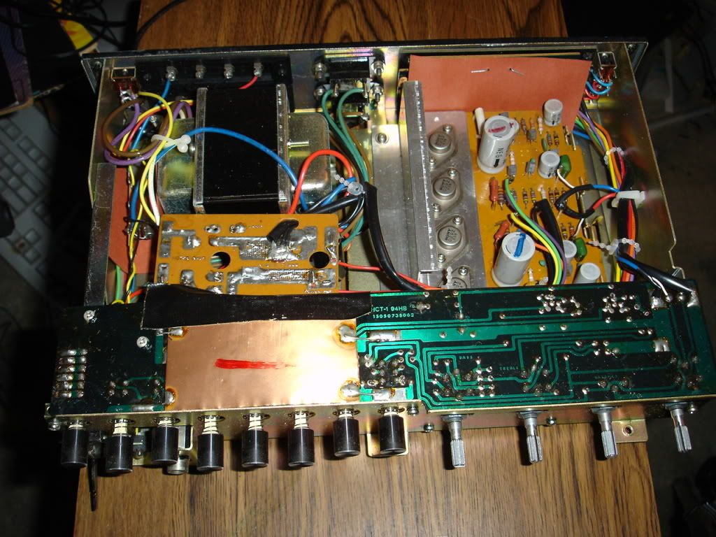
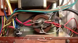
I've replaced all the caps in the power-supply and all the electrolytic caps on the amp board.
Aside from safety (the amp hummed), the caps where also way to small in capacity.
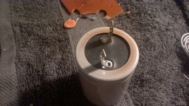
The power-supply cap was 2200uf + 470uf on a toasted piece of PCB
These caps are now hard wired 4700uf + 1000uf caps.
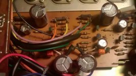
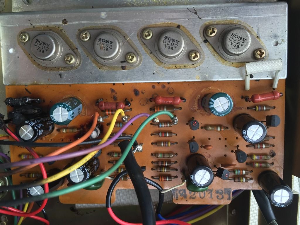
The large grey caps on the main amp board are the output decoupling caps for the speakers and these where only 470uf (not a typo😱).
Also the input decoupling cap was only 100n in about 47k of resistance (green cap on the board above) and the bootstrapping and feedback cap where 47uf.
I've replaced the output decoupling caps with 2 x 1000uf caps in parallel and all the other caps with 220uf.
The input decoupling cap is now a Philips orange-drop of 470n
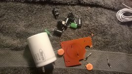
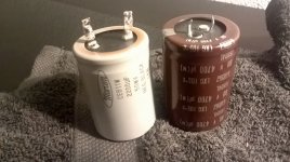
I've managed to replace all the caps with (new) the same brand (Nippon Chemicon) electrolytics
so technically I've kept it as original as I could without buying any new components.
I've deliberately chosen NOT to recap the whole filter board (project for another time perhaps)
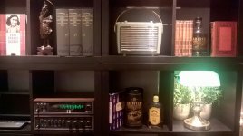
The amp play's fine now (without any hum) serving as a book case amp once again!
See the pictures below:
I've replaced all the caps in the power-supply and all the electrolytic caps on the amp board.
Aside from safety (the amp hummed), the caps where also way to small in capacity.
The power-supply cap was 2200uf + 470uf on a toasted piece of PCB
These caps are now hard wired 4700uf + 1000uf caps.
The large grey caps on the main amp board are the output decoupling caps for the speakers and these where only 470uf (not a typo😱).
Also the input decoupling cap was only 100n in about 47k of resistance (green cap on the board above) and the bootstrapping and feedback cap where 47uf.
I've replaced the output decoupling caps with 2 x 1000uf caps in parallel and all the other caps with 220uf.
The input decoupling cap is now a Philips orange-drop of 470n
I've managed to replace all the caps with (new) the same brand (Nippon Chemicon) electrolytics
so technically I've kept it as original as I could without buying any new components.
I've deliberately chosen NOT to recap the whole filter board (project for another time perhaps)
The amp play's fine now (without any hum) serving as a book case amp once again!
See the pictures below:
Attachments
-
 WP_20151018_19_15_19_Pro.jpg432.7 KB · Views: 508
 -
 WP_20151019_20_47_41_Pro.jpg358 KB · Views: 510
 -
 WP_20151019_21_47_25_Pro.jpg553.5 KB · Views: 471
 -
 WP_20151019_21_47_37_Pro.jpg395.4 KB · Views: 431
 -
 WP_20151019_21_48_28_Pro.jpg425.6 KB · Views: 356
 -
 WP_20151020_23_09_30_Pro.jpg377.7 KB · Views: 358
Last edited:
@Nigel Goodwin, there is no imagination involved here. Have you never had elcaps explode when you hit the power switch? Old caps actually dry out, even without obvious signs of leakage and will often short the rails after lying idle for many years, sometimes resulting in an incredibly loud explosion, filling the room air with tiny aluminium foil fragments. A repair technician acquaintance of mine became permanently deaf in one ear due to such an accident. It's happened to me about a dozen times as I have been repairing old electronic equipment periodically for more than forty years, with and without variacs or other safety aids. These were US, Japanese and UK parts IIRC, in various consumer and pro test gear. Now I use an in-circuit ESR meter to avoid the shock, pain and incredible mess. That to me, is a convenient way find the real condition of caps and avert what is clearly a personal safety risk.
There are also many threads here which identify the timing caps in relay protection circuits as the reason for erratic or failed power-up in amplifiers (including older HT receivers). That's just one cap usually but since it is critical to getting the amplifier to work, its deterioration is very noticeable while the many other caps that are probably just as bad go unnoticed. Food for thought?
When I replace identical caps, I sometimes weigh or just feel the significant differences in mass that can only be down to liquid or vapour loss. Seals are not perfect and the heat inside some brands of amplifier, particularly the small, poorly ventilated designs you may be more familiar with, is often unacceptably high when used in this country. 50-55C is well within the specification of most caps but where this is related to warranties of perhaps 2,000 hours operation or less, you can see the problem - regardless of whether you trust experience and luck over specs.
Captain archer, good result. The output coupling cap could go even higher but on checking the limited available specs, this is only an 8W+8W RMS rated amplier. I'd be careful not to turn it up with bass-heavy material. FWIW, I have the remains of a similar small design TA88. The small transformer on this which looks quite similar, burnt out when the owner fitted a 4,700uF output cap. Maybe just coincidental, but there it is.
@Nigel Goodwin, there is no imagination involved here. Have you never had elcaps explode when you hit the power switch? Old caps actually dry out, even without obvious signs of leakage and will often short the rails after lying idle for many years, sometimes resulting in an incredibly loud explosion, filling the room air with tiny aluminium foil fragments.
No, never had it happen - although I'm aware of the potential on antique valve equipment, where you should 'reform the main electrolytic capacitors' before applying normal power.
As far as I'm aware, from decades of personal experience (and of thousands of other engineers experiences) it's not a problem on small transistor amps. It's also not a problem on small coupling caps either 😀
Some of us do this as a job IE we make money repairing amplifiers Thank god people like Nigel exist ...Its the best way to make even more money ....
Kind regards
Sakis
PS if you would like Nigel i could send you for free about 20.000 electrolytics that we replaced this year ( any size ) Obviously you may measure them and see with your own eyes ..Though i don't really know if it will be possible to measure before or after you remove all the chemical left overs from the pins ....Alternative will also be to drill them from the top and add juice inside them since the old one evaporated years ago
Hi all (@Ian Finch and @Captain Archer),
Was after the schematics as per the OP.
I recently purchased a Sony TA-70. It came with the ST-70 and primarily a Turntable (Sony PS-1100). At the time I was aware that the Amp only had one working channel, the LEFT, but was happy.
Last night whilst listening to some records the sound stopped for a bout 10 seconds, then came on accompanied by the smell of magic smoke! I unplugged it all quickly and got the Amp outside to air out.
This morning I opened the case and found this on the main board for the Amp:
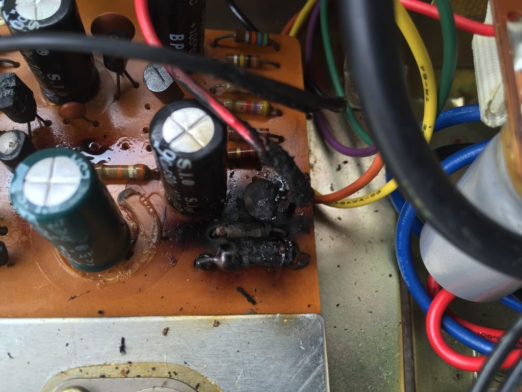
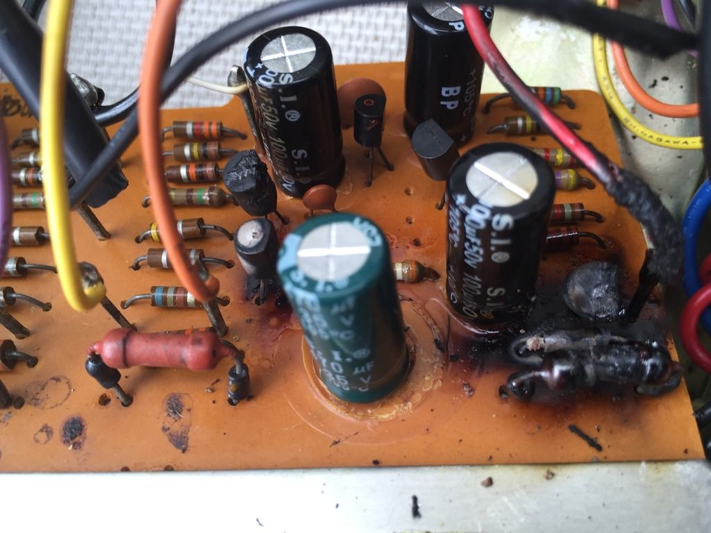
...so, I would love to get hold of the schematic so I can identify properly some of the parts that are about to go (some of those resistors have gotten very hot!) and replace the ones that are black crispy things!
Was after the schematics as per the OP.
I recently purchased a Sony TA-70. It came with the ST-70 and primarily a Turntable (Sony PS-1100). At the time I was aware that the Amp only had one working channel, the LEFT, but was happy.
Last night whilst listening to some records the sound stopped for a bout 10 seconds, then came on accompanied by the smell of magic smoke! I unplugged it all quickly and got the Amp outside to air out.
This morning I opened the case and found this on the main board for the Amp:
An externally hosted image should be here but it was not working when we last tested it.
...so, I would love to get hold of the schematic so I can identify properly some of the parts that are about to go (some of those resistors have gotten very hot!) and replace the ones that are black crispy things!
Can anyone suggest what to do about maybe replacing some of the small transistors? I see in the photos above that newer ones have been put in place. Are there any advantages to replacing old ones even if they are still working properly?
If I were to select from BC546 or BC550 to replace the C634As, should I be concerned about the BC550 being 45v rated vs the BC546 rated for 50v?
I'm trying to maximize the sound quality and also get rid of the mild low volume hiss mine has.
thanks,
M
If I were to select from BC546 or BC550 to replace the C634As, should I be concerned about the BC550 being 45v rated vs the BC546 rated for 50v?
I'm trying to maximize the sound quality and also get rid of the mild low volume hiss mine has.
thanks,
M
Replacing transistors wont buy you better sound quality and I would also doubt that it would improve the hiss.
The BC546 is a 65 volt device. Not sure what the 2SC643A variant is rated at but the 634SP is rated at 52 volts.
I wouldn't change semiconductors on a whim. Sometimes these old designs rely on the rather pedestrian performance of the transistors as a means to ensuring the circuit is stable. That applies particularly to output and drivers.
Thanks for the reply. Apologies for the typo - the transistors are C634A, not C643A.
I believe they are 50v rated. I found a couple suggestions for replacements: BC546, 2SC1815. The BC550 is a low noise version of BC546, but rated slightly lower in voltage, so I thought they might be a good selection, but I'm guessing here. I have no experience with this kind of thing. This is my first attempt and restoration/improvement.
thanks again,
M
Attachments

Last edited:
Sorry, I typed the wrong number but looked at the 634 data sheet.
Just looking in an old T.D. Towers book and that shows the 634A as being 50 volt. Equivalents back in the day being shown as BC347A and 2N3903.
Noise in line level and power amps (as opposed to dedicated high gain low level circuitry such as moving coil phono amps) is mostly determined by the circuit topology and how the gain structure is organised stage to stage.
By all means try replacements but I doubt they will reduce hiss.
TA-70
any one needing a copy of the service manual go to hifiengine.com where I uploaded it or pm me for a copy. jim
any one needing a copy of the service manual go to hifiengine.com where I uploaded it or pm me for a copy. jim
Thanks Jim. That should help those owning one of these.
Edit... just had a look.
It seems the power amp runs a fixed bias scheme and so replacing the drivers (and or outputs) could seriously affect the biasing. The good news is that it seems to have a proper bias generator and so could have one of the resistors swapped out for a preset.
Edit... just had a look.
It seems the power amp runs a fixed bias scheme and so replacing the drivers (and or outputs) could seriously affect the biasing. The good news is that it seems to have a proper bias generator and so could have one of the resistors swapped out for a preset.
- Status
- Not open for further replies.
- Home
- Amplifiers
- Solid State
- Sony TA-70 schematic / manual?