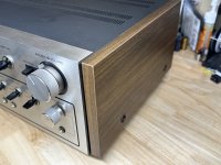
I picked up a TA-5650 in good to very good cosmetic condition that played music in both channels, but typical scratchiness turning the volume pot. I figured this piece is definitely worth a full dose of TLC to restore it.
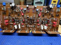
Still in the process of working on the main amp board. So far it's been recapped, death diodes replaced and some resistors swapped.
This is a good time to formulate a plan to replace the OEM speaker spring clips with 5-way binding posts. BUT, the puny 22ga hookup wire is driving me crazy!
I plan on replacing the output relay and main filter caps.... While the chassis is open, should I take this opportunity and rewire the full output path from amp board -->output board -->binding posts with 18ga flexible silicone jacket wire?
Or should I suppress the urge to replace the 22ga and move on.... 🙂
- All the VFETS were pulled and tested - All good here
- Power supply board recapped and D405 series diode mod installed.
- EQ amp, selector, tone control and filter boards recapped and all switches and pots cleaned and lubed (where needed).
- All solder joints reflowed and pcb's thoroughly cleaned and flux residue removed. They were pretty messy from Sony, especially the amplifier board.
Still in the process of working on the main amp board. So far it's been recapped, death diodes replaced and some resistors swapped.
This is a good time to formulate a plan to replace the OEM speaker spring clips with 5-way binding posts. BUT, the puny 22ga hookup wire is driving me crazy!
I plan on replacing the output relay and main filter caps.... While the chassis is open, should I take this opportunity and rewire the full output path from amp board -->output board -->binding posts with 18ga flexible silicone jacket wire?
Or should I suppress the urge to replace the 22ga and move on.... 🙂
Attachments


Keep in mind that if the A+B option is choosen, B is switched in series on top with A (A- is always on ground).
Added 5650_interconnects for a clear view of the wiring (you have version 1b or 2).
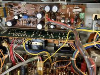
All the eight ground wires are bundled under the yellow ring terminal - the input ground of the main pcb is routed via the RCA connectors and arrives at the same point under the red ring terminal.
Added 5650_interconnects for a clear view of the wiring (you have version 1b or 2).
All the eight ground wires are bundled under the yellow ring terminal - the input ground of the main pcb is routed via the RCA connectors and arrives at the same point under the red ring terminal.
Attachments
The 'version 1b + 2' wiring diagram is incredibly helpful, Thank you @Citizen124032!
The method of selecting outputs is different than I've seen in other gear.
Armed with this additional documentation, seems as though I'm heading for a rewiring project 😉.
Just purchased all the wire needed in correct colors to keep consistency with schematics.
The method of selecting outputs is different than I've seen in other gear.
Armed with this additional documentation, seems as though I'm heading for a rewiring project 😉.
Just purchased all the wire needed in correct colors to keep consistency with schematics.
Last edited:
In the ServMan the separation of the versions is noted on the page of the circuit diagram by Serial Numbers.
I suspect two reworks: the groundings and some component values.
Hence the 1a (orignal), 1b ('regrounding', but not in the SN's) and 2 (comp values).
I suspect two reworks: the groundings and some component values.
Hence the 1a (orignal), 1b ('regrounding', but not in the SN's) and 2 (comp values).
That's to protect the output V-fets from overcurrent demands from the speakers as most folks think opportunistic.The method of selecting outputs is different than I've seen in other gear.
Thanks Citizen!
Working on vintage gear is a nice change of pace from “new builds” and provides different challenges.
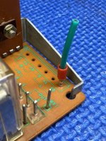
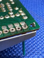
Since the heavier gauge wiring will not be able to be wire wrapped, a different connection method must be used. With the pin header removed an 18ga wire ferrule crimp almost fits in the holes. By slightly enlarging the hole (<0.5mm) the ferrule fits perfect and will be a clean install when all the wiring is swapped.
Working on vintage gear is a nice change of pace from “new builds” and provides different challenges.
Since the heavier gauge wiring will not be able to be wire wrapped, a different connection method must be used. With the pin header removed an 18ga wire ferrule crimp almost fits in the holes. By slightly enlarging the hole (<0.5mm) the ferrule fits perfect and will be a clean install when all the wiring is swapped.
Attachments
Hmm... serviceability decreases with this eternal fixation.
I prefer (pluggable) terminal blocks as provided by reliable brands only, not the cheap (mostly) oriental ones with 'anymetal', supposed to conduct but act as isolators instead.
Anymetal is forged in a melting pot from any leftover metal parts, whatever the compound and/or the origin. Iron, copper, lead, zinc, tin, aluminium, and what not.
Another hmm. I tried exactly that and was not happy with the result. Ferule is perfect for screw terminals but solders poorly. Instead, I’m using this turret terminal. Accepts 14ga wire. However, pin has 1.8 mm diameter.
https://hr.mouser.com/ProductDetail/855-H9026-01
https://hr.mouser.com/ProductDetail/855-H9026-01
Good feedback fellas, I’m not sold on my proposed solution either. I prefer to use mating connectors.
With more poking around, it almost makes sense to design a new output board (in the same shape) that will accept proper headers for the upgraded wiring. Maybe even replace the mechanical relay with a solid state relay circuit.
The rectifier board will also need some attention….🤔
With more poking around, it almost makes sense to design a new output board (in the same shape) that will accept proper headers for the upgraded wiring. Maybe even replace the mechanical relay with a solid state relay circuit.
The rectifier board will also need some attention….🤔
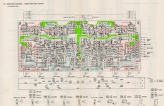
In addition of #3, the main board but with the grounds coloured green. It explains why there are three ground connections.
The image has been pickup from DIYaudio a while ago. It is the '1a' version, but not different by design.
Also attached, with green grounds (from diya ditto) & D405 indicated for the 'balance'modification (and preferred ground point).
The image has been pickup from DIYaudio a while ago. It is the '1a' version, but not different by design.
Ouch! A triac (or an anti parallel thyristor) in series with the output. Mechanical ry's are reliable, your part is 50 years old. Maybe a (high current) reed relay serves you better....replace the mechanical relay with a solid state relay circuit.
There are a lot of posting about the 5650 on DIYaudio, also the Rect Brd is addressed.The rectifier board will also need some attention…
Also attached, with green grounds (from diya ditto) & D405 indicated for the 'balance'modification (and preferred ground point).
Attachments

Our vfet expert @ilimzn recommends replacement of all fusible resistors, post here: https://www.diyaudio.com/community/...vicing-before-powering-on.319151/post-5349911
Are there any fusible resistors in the 5650?
Are there any fusible resistors in the 5650?
I was able to buy a 5650 in working condition, all the vfets test good 🙂
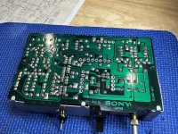
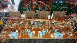
I think there are fusible resistors in this unit, they are all the resistors that have long leads (raised above the board). They have a different color too. (See attachment.)
I'm looking at a lot of work here (recap, diodes, etc)
I think there are fusible resistors in this unit, they are all the resistors that have long leads (raised above the board). They have a different color too. (See attachment.)
I'm looking at a lot of work here (recap, diodes, etc)
Attachments
They're not documented as such in the ServMan, but you've answered your own question already.Are there any fusible resistors in the 5650?
The 5650 has four suicide diodes on board (the 4650 only three) - these are the utmost prominent replacement parts.
I recommend to replace C308/309/358/359 with bipolars.
Notice there are two versions in the field, distinct by the serial numbers - inner wirings differ too (interconnects).
Do you have the three (dutch) service bulletins?
I've translated the two important ones & posted them in another thread already but it won't hurt if made available again.
Attachments
Thanks, very helpful.
I have read a number of posts with important advice on these amps, for example: don't power it with the input disconnected from the amp board (it is the only ground reference for the power amp).
I have read a number of posts with important advice on these amps, for example: don't power it with the input disconnected from the amp board (it is the only ground reference for the power amp).
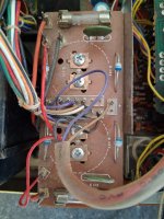
The rectifier board of my TA-5650 (US version - series # 800...) is a little different from some I've seen here on the forum.
There is only 1 brown cable coming from the bottom connectors to the power supply, the other brown cable that goes to the amplifier board comes from the right center row of pins.
Also, the red cables that go to the power supply board are very close to the secondary inputs.
Do these 2 red cables carry AC to the power supply/voltage doublers? What is the AC voltage, assuming it is the same as the transformer secondaries?
Has anyone tried a CLC filter as suggested by Andrea Ciuffoli - Audiodesigngide?
Tks!
Attachments
Last edited:
- Home
- Amplifiers
- Solid State
- Sony TA-5650 RestoMod