Hey guys I'm in need of some help. I have a Sony str-d965 a/v receiver that will not come out of protect. When I got it the left channel transistors where shorted collector to emitter so I removed them and still went to protect. So when I got the new ones installed, still protect. I call myself checking all bias transistors and emitter resistors and over load set circuit but can't find anything wrong. So I checked voltage on protect line, which should be 5.2v according to schematic and I only have 0.8v. But when I remove ribbon cable to display board my protect line comes back to 5.2v. So I'm really not sure why it is going into protection. I have schematic if I need to post it. I really want to figure this out.
First thing to check is whether there is a DC offset present on the main amplifier outputs (measured before the speaker relay). I would bet that there is.
Thanks mooly for the quick reply. With the power on and it flashing protect I looked for voltages on the emitter resistors and they all read zero volts. Do I need to check in milli-volts? When I measure transistors directly I have 58v and -58 and on the bases I have 1.1 and -1.1 and the collectors read 0.
There should be zero volts on the emitters, +/- 1.1 volts on the bases and +/- 58volts on the collectors.
Have you replaced.checked the cause for the failure yet?
Have you replaced.checked the cause for the failure yet?
It would help to see a circuit of the output stage.
Those voltages at face value don't immediately suggest a problem. -/+58 on the emitters and zero on the collectors suggest the output stage uses a CFP configuration of some sort rather than the more usual emitter follower type.
You need to look at the 'inputs' to the protection circuit to see if any are in a state that would trip the protection.
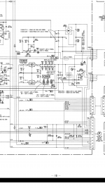
Sorry guys I said those pins wrong. Bases are correct +/- 1.1 v collectors +/-58v emitters are 0. But here is a screen shot of amp output board.

Hmmm 🙂
You have five power amplifiers on that page, three discrete channels and two 'chip amps' using LM3875's.
You need to measure the DC voltage at the output of all five, and all should be zero.
You have five power amplifiers on that page, three discrete channels and two 'chip amps' using LM3875's.
You need to measure the DC voltage at the output of all five, and all should be zero.
Ok will check the chip amps and see what they say. Thanks again for all the help. I'm about to go to work so I will get back when I get home tonight.
You need to check all five power amps. Any that have a significant DC offset will trip the protection circuit.
All right finally had some time to mess with the amp some today. I checked all five outputs on 20v scale of my dmm and I have .23v on every output from all transistors and the 2 lm3875 chip amps. Reason i didnt notice before is because my next scale is 200v on my meter. So now that you guys have helped me discover i have a dc offset, how would I got about tracking down what is causing it? I have a stk3102-3 and an stk350-130 ic's also.
The STK chips are high voltage amplifiers, not really power amps in their own right.
The 0.23 volt 'offset' sounds off because it is a bit low to cause problems and yet to high in its own right. Also to see the same offset on all five power amps suggests a problem in the measurement somewhere.
Recheck just one of the LM3875's to begin with.
Put your meter black lead on ground and check the voltage on the chip output. This is a DC voltage measurement.
It can safer measuring on nearby parts rather than attempting to prod the chip itself. One short and it all goes pop.
Look at the circuit. You can check the offsets accurately for all five amps by measuring across:
1/ C676
2/ C626
3/ C704
4/ C754
5/ C604
Ok I checked at the capacitor points you recommended and I still get the .23 v on all cap points from all channels. But I found a pin that wasn't soldered well on the plug going to the display board it is labeled 4-8 so after resoldering my base voltages went to 1.23 and -.87 and all emitter resistor points are giving me the .23v. But if I subtract 23 from 1.23 and add 23 to .87 I will get what the base voltages are supposed to be which is +/- 1 volts. So I'm still lost on what's going on.
Seeing 0.23 volts DC on all five stages (and those stages are a mix of discrete and chip amp) simply doesn't compute tbh.
You can't go any further until this anomaly is resolved because it throws doubt on all other readings.
Are you sure your meter reads zero when the leads are shorted ?
This may sound silly but do those voltages drop to zero when the amp is OFF or do you still read 0.23 volts ?
If nothing obvious emerges then you need to do a careful measurement on one of the LM3875's and see what is going on.
Pin 1 should be at near to zero volts. Check it. Measure on one of the components connecting to pin 1 for safety.
Pin 2 should also be at near zero but will probably not be with this 'offset'.
Ok I figured out my offset issue. I had removed the volume control board upon testing and that's what was giving me my .23 offset on all channels. So now that I put it back in all my voltages ate back to normal with +/- 1v on bases and +/- 58v on collectors and 0v on all emitters. Both chip amps have 0v on output as well. But still going into protect. I'm starting to wonder if the system control chip on display board is bad cause if I unplug ribbon cable from amp to display board my protect circuit comes up to the 5v needed to keep protection off. Q711 q712 and q713 all test fine. But even with unit off and I plug ribbon cable in it immediately drops to .8v on protect circuit.
Good to know the offset issue had a real cause and is fixed.
So you need to find out if the problem is on the amp board or elsewhere.
What is the DC voltage across C711 ?
What is the DC voltage across C712 ?
Both should be zero. If either is at 0.6 to 0.8v then the problem would appear to be around the circuitry on that board.
So you need to find out if the problem is on the amp board or elsewhere.
What is the DC voltage across C711 ?
What is the DC voltage across C712 ?
Both should be zero. If either is at 0.6 to 0.8v then the problem would appear to be around the circuitry on that board.
I checked across c711 and c712 with black lead on - of cap and red on + of each cap. And both have zero volts across them.
Interesting.
You are going to have to be creative to find this. You need to isolate just the C4 protection line and see if the level comes up at its destination (which is off the sheet).
You have to decide whether it is being pulled down by the audio board or not.
Is D714 OK (not leaky) ?
You are going to have to be creative to find this. You need to isolate just the C4 protection line and see if the level comes up at its destination (which is off the sheet).
You have to decide whether it is being pulled down by the audio board or not.
Is D714 OK (not leaky) ?
I have checked d714 by removing one leg from the circuit and checked good .5 to .7 drop one way, and nothing the other. I lifted one leg on d710 to isolate the overload det circuit but still dropped to .8v. Looks like c4 gets power from 5.7v rail through r732 10k resistor and with unit on I get 5.85v on one side and .8v on the other. But out of circuit it test 10k ohms. Also have checked all diodes to the right all the way to "F" connector tapped off of c4 line. All test good. Also have removed r714 and c711 and still drops to .8v when F is plugged in and unit on or off.
Attachments
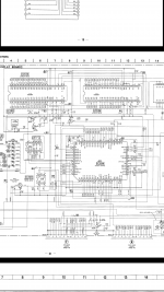
You need to isolate just pin 5 of that connector so that the protection line floats. You can do that easily by lifting D716.
Now see what the voltage is on D716 anode. It should be 5 volts.
Make sure that C111 on pin 26 of the system control chip isn't leaky and also make sure that there is continuity from pin 26 back to D716.
Now see what the voltage is on D716 anode. It should be 5 volts.
Make sure that C111 on pin 26 of the system control chip isn't leaky and also make sure that there is continuity from pin 26 back to D716.
Everything checked out as you said. When I lifted d716 5v was there and with voltage drop on other side was correct also. Continuity is there from pin 26 to pin 5 on F connector. C111 is a resistor style cap but according to meter checks good btw I don't have an esr meter. But when unit is off on q713 e and b I have -.49v and c=5.75v. Q712 b=.07v e=0 c=5.75. But when unit on q713 e=-58v b=-49v c=5.75v q712 b and e =0v c=5.75v.
- Status
- Not open for further replies.
- Home
- Amplifiers
- Solid State
- Sony str-d965 receiver help