I recently acquired a sony scd-xb770 sacd player and am planning to install a new clock. The master clock is located on the audio board and runs at 11.2896MHz and clocks the 3 multibit delta sigma dacs directly (CXD9658N) and then is multiplied by 3 to 33.8688MHz for the DSD decoder IC (CXD2752R) The multiplier uses a 74LVU04A with a cap (22pF) and inductor (1uH) parallel resonant circuit connected directly across the input and output of each of 3 inverters, the inverters are then connected in series through small resistors. Obviously these filters must be tuned to the 3rd harmonic of the master clock. Does this circuit achieve a good lock to the master clock? I am a little sceptical actually.
What I am wondering is just how jitter prone is this clock multiplier circuit and given that I am not going to be using the dacs on the audio board much once I tap the dsd stream would it make more sense to divide a 33.8688MHz master clock down for the dacs?
Also does anyone have any information on the CXD2752R or the CXD9658N? Data sheets or/and crosses to non-proprietary part numbers?
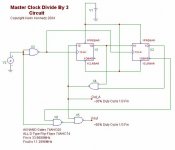
See the schematic below:
What I am wondering is just how jitter prone is this clock multiplier circuit and given that I am not going to be using the dacs on the audio board much once I tap the dsd stream would it make more sense to divide a 33.8688MHz master clock down for the dacs?
Also does anyone have any information on the CXD2752R or the CXD9658N? Data sheets or/and crosses to non-proprietary part numbers?
See the schematic below:
Attachments

Personally I would go for a low jitter 33.8688 MHz clock and divide by three with two D-type flip-flops. Horowitz page 513.

Hi Elso,
Thanks for your input, it pretty much confirms what I have been thinking might be the way to go.
I will use a two stage synchronous counter use an AND gate and AND the Q outputs. I initially thought to use JK type flip-flops, but noted that the 74HC74 D type clocks on the rising edge of the clock. Also what about the duty cycle of the divided clock?
So far what i am seeing with D type flip-flop does not look like a good clock source.
I will post something once the model seems to work correctly. 😀
I don't have access to Horowitz & Hill so if you have a specific suggestion as to topology could you post here?
I got an implementation that looks like it works ok with 2 JK flip flops and an AND gate.. Produces 50% duty cycle clock output at 1/3 Fin. Will look at implementing with D type flip flops later. This is modeled of course. 😀
comments on divider?
Came up with d type implementation. Short of unexpected gate delays I should be able to get 50% duty cycle clock if that matters, otherwise edges are in right place on alternative output.
Circuit has been heavily simulated, does not seem to be particularly sensitive to clock speed within the allowed limits of the devices used. Note I have not yet built.. Will design pcb using smd passives and soic package logic.
And anyone have any comments. Thanks Kevin
Attachments
Manual or schematics
Hi
I am planning to sustitute the original clock in ..XB770 with LCaudio XO3. I have problems though getting the service manual to this player. Is there any chance you sharing this manual? It would be much appreciated!
Regards
Hi
I am planning to sustitute the original clock in ..XB770 with LCaudio XO3. I have problems though getting the service manual to this player. Is there any chance you sharing this manual? It would be much appreciated!
Regards
Yes I would be happy to share the service manual with you.. I have it as a pdf file which is fairly large.. I can email it to you if you contact me privately off the board..
Thank you!
Since you do not want allow emails from this forum I have contacted the adminstrator so I can email you from there.
Regards
kva
Since you do not want allow emails from this forum I have contacted the adminstrator so I can email you from there.
Regards
kva
servicemanual XB770
Hi kevinkr,
I would greatly appreciate receiving the PDF file of the servicemanual.
Unfortunately you have disabled the email button in your profile hence this post. Please contact me by hitting the email button below this post and I will reply with my email address capable accepting a large file. Sounds a bit complicated but is in order to keep the account free of spam.
Thanks in advance.
Re: comments on divider?
Hi Kevin,
VHC logic is giving less glare in digital circuits than AC or HC logic. The 50% duty cycle is probably not necessary as the player would also work with the 30%.
kevinkr said:Came up with d type implementation. Short of unexpected gate delays I should be able to get 50% duty cycle clock if that matters, otherwise edges are in right place on alternative output.
Circuit has been heavily simulated, does not seem to be particularly sensitive to clock speed within the allowed limits of the devices used. Note I have not yet built.. Will design pcb using smd passives and soic package logic.
And anyone have any comments. Thanks Kevin
Hi Kevin,
VHC logic is giving less glare in digital circuits than AC or HC logic. The 50% duty cycle is probably not necessary as the player would also work with the 30%.
Hi Elso,
Thanks for the tips, I will look into the vhc logic family. I thought it was probably the case that the clock inputs are edge triggered. One more thought: is there any reason why I couldn't just have two separate XO with the required frequencies and not use the divider at all? Cost wise for me this would probably be a wash...
Thanks, Kevin
KVA:
Have you had any luck getting my email address from a moderator? If not try me at kennedykr2004@nospam.yahoo.com
Just remove "nospam" from the address to reply and I will send you my real email address.
Kevin
Have you had any luck getting my email address from a moderator? If not try me at kennedykr2004@nospam.yahoo.com
Just remove "nospam" from the address to reply and I will send you my real email address.
Kevin
kevinkr said:Hi Elso,
Thanks for the tips, I will look into the vhc logic family. I thought it was probably the case that the clock inputs are edge triggered. One more thought: is there any reason why I couldn't just have two separate XO with the required frequencies and not use the divider at all? Cost wise for me this would probably be a wash...
Thanks, Kevin
Hi Kevin,
Yes edge triggered.
I am afraid the two clocks must be synchronized.
Hi Elso,
I thought this might be the case so I will proceed with my divider as planned, and I will use the newer VHC series logic in my design..
Thanks, Kevin
I thought this might be the case so I will proceed with my divider as planned, and I will use the newer VHC series logic in my design..
Thanks, Kevin
XB770 mnual
Kevinkr!
Thank you for the manual. I have successfully downloaded the pdf-attachment. Now I am going to work.
Regards
Kva
Kevinkr!
Thank you for the manual. I have successfully downloaded the pdf-attachment. Now I am going to work.
Regards
Kva
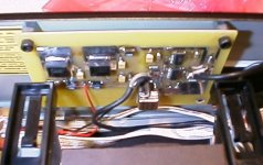
Let me know how your project is going.. My clock board is all built and I have a couple of spares.. Still waiting for the tentlabs master osc.. Once I get the thing going I will post the results here.
Success
Yesterday I installed the board I made and connected the 11.2896MHz output to the dacs and 33.8688MHz master clock to the main board dsd decoder and some other related ics.
I used the output directly from the divider which has a 30% duty cycle - my scheme for 50% did not work well due the short propagation delays throught the VHC logic I used in the design. I fortunately made this option defeatable and provided two output phases of the 11.2896MHz clock relative to the 33.8688MHz clock instead.
The pcb is installed behind the tray and I carefully removed the power supply pcb and tapped into the raw 7.2VDC unregulated supply directly at C904 to power the two fairchild FAN series regulators on the pcb. I took the ground from this point as well.
On the audio pcb I removed the 11.2896MHz crystal, the 100 ohm resistor R325 and C303 and connected the clock to the side of the crystal going to IC304 pin 1.. I used a 50 ohm shielded cable grounded at the clock board only to inject the signal into the audio board.
I tested the unit with just these changes and there seemed to be a definite reduction in grain on CD and SACD alike.
Now for the scary part - I carefully removed L803, and C852 which are on the top side of the main board, by the DSD decoder IC and R858 on the bottom side of the pcb. I injected the 33.8688MHz clock into the IC 811 pin 5 side of L803. I used a shielded 50 ohm cable here as well.
I know many here have said NOT to use a shielded cable, but frankly 12cm of unshielded wire with 33MHz and 11MHz @ 3.3Vpp near the audio circuitry does not fill me with enthusiasm.. I tried both and frankly heard no difference.
I wanted to make sure these changes were fully reversible so I removed only the parts required to make things work... There are a number of components I will eventually remove in the old clock muliplier circuit on the main board in order to reduce potential interference issues in IC811.
In terms of sound I can say there is much less grain and the bass does sound a little more defined.. This was as DIY modifications go, quite expensive, and I have not yet convinced myself that this was money well spent... (Overall cost about $150.00)
I had a lot of fun doing it, although I will say hacking around on those static and short sensitive pcb's left me feeling very anxious! This model is not sold here and replacement parts would be difficult to get.
The audio/dsd side of things needs lots of attention as well, and that will be my next focus..
Finally I may experiment with better electrolytics (OSCONS) in the power supply of the clock pcb as these are currently all tantalum smd types chosen for low impedance and relatively low cost.
Attachments
I removed the components I mentioned earlier in the clock multiplier and the difference was fairly obvious..
Remove L801, L802, C850, C851, and R880.. Install a jumper from pin 1 to pin 7 of IC811 - this completely removes all vestiges of the old multiplier circuit and any possible supply/clock line artifacts it might be generating.
I also changed the clock phase of the 11.2896MHz clock which in this case might equate to nothing more than about a 44nS shift in clock edge relative to the 33.8688MHz clock, but it sounded better... It does isolate external capacitance from the flip-flops so that might have some bearing on what I heard as well..
I am going to do a quick bypass on the 2CH outs only directly back to the op-amps to see what improvement that might effect.
I don't know if anyone is following this thread at all.. LOL However I did disconnect the 2CH rca jacks and used 1K roederstein resistors directly from the outputs of the op-amps to the jacks, after removing R410, R510, C407 and C507. Those capacitors are 100pF ceramics and while they are there to reduce emi escaping from the player, they do nothing good in terms of the sound.
The improvement from making this change was very worthwhile in addition to the clock system upgrades.
The player sounds a lot better at this point, and despite the expense seems to have been a good move overall..
I do need a much better analog section which is coming next.
To recap the XO used in my clock board came from TentLabs. The clock system board I designed runs at the 33.8688MHz of the XO and there is a D flip-flop based divide by 3 circuit to get the 11.2896MHz clock which is used by everything in the player except the CPU and DSD decoder. The CPU uses its own 20MHz crystal and the DSD decoder uses the level translated XO clock.
The XO runs at 5V, is level translated to 3.3V for the player and the divider circuitry. There are two low noise fairchild regulators with choke decoupling and lots of ceramic and tantalum supply decoupling caps located so as to minimize loops.
Use anti-static precautions if you are contemplating doing anything similar.
The service manual is available on the web if you search for it.
A friend and I spent the day today listening to the improved sacd player and after several hours to warm up the differences could be summed up as a large reduction in graininess, better, more tuneful bass, and a considerable increase in overall resolution.. Also much less fatiguing to listen to.
I definitely recommend this upgrade path as a viable option to the more skilled and intrepid diy'er..
I definitely recommend this upgrade path as a viable option to the more skilled and intrepid diy'er..
- Status
- Not open for further replies.
- Home
- Source & Line
- Digital Source
- SONY SCD-XB770 Clock Mods