Recently I was given for free a Sony RCD-W3 with the following symptoms, CD recorder drive reads CDs without any issues (haven't tested recording function yet because I don't intend to burn CDs on that machine) but the reader drive shows disc error after some seconds of it trying to read CD. Tried both CD-Rs and commercial audio CDs with same results.
First thing to do was to clean the lens but that didn't change anything. Googling the issue revealed that this is a common issue on several Sony CD recorder machines and the culprit is SMD electrolytic caps located on the PCB bellow the drives going bad.
I decided to check every single cap on that machine with my ESR/capacitance meter.
All the caps on the power supply board were found OK.
On the green PCB that hosts the back panel audio connectors all the caps were found OK except a visibly bulging Licon capacitor that is located next to the relay, so I replaced that cap.
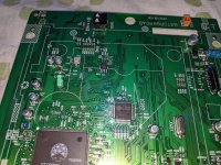
Then, very carefully removed the 2 optical drives. You should try to remove the 2 CD drives and the PCB bellow them all together as 1 piece and not do as I did. There are flex cables bellow the optical drives that make it very difficult to work while the PCB and the drives are still inside the device.
Anyway, after carefully disconnecting the flex cables and removing the optical drives, I checked every SMD electrolytic capacitor with my ESR meter and found several of them to be bad, most of them totally open! I am really grateful that none of them leaked electrolyte on the PCB.
I decided to replace the caps with used capacitors I have pulled out of other machines, because the device is of no special value to me, economical or sentimental, so I didn't want to spend money on the repair. I also replaced only the caps that were found bad upon testing in circuit. There is a chance that there might be more bad caps there but due to being connected in parallel with other caps, the ESR meter was not able to detect it.
If your unit is important to you, it's better to try to replace all the capacitors on that board, using caps from known Japanese manufacturers rated for 105C, general purpose or entry level low ESR and definitely not ultra low ESR as that might detune the circuit. I used a mix of 85C and 105C capacitors that I first tested to make sure they didn't go bad in storage. Total number of caps replaced: 14
Number of caps left alone: 20
After the recap, reconnected everything paying attention not to damage the flex cables or break a connector.
Finally, I connected it to AC mains and made sure both drives now work without any issues!
The only issue that I found is that when I play extremely scratched CDs I get audible jitter, mainly on the repaired drive but also on the recorder drive on some occasions.
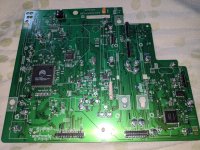
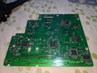
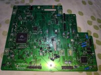
I attach some before and after pics of the repair for reference
First thing to do was to clean the lens but that didn't change anything. Googling the issue revealed that this is a common issue on several Sony CD recorder machines and the culprit is SMD electrolytic caps located on the PCB bellow the drives going bad.
I decided to check every single cap on that machine with my ESR/capacitance meter.
All the caps on the power supply board were found OK.
On the green PCB that hosts the back panel audio connectors all the caps were found OK except a visibly bulging Licon capacitor that is located next to the relay, so I replaced that cap.
Then, very carefully removed the 2 optical drives. You should try to remove the 2 CD drives and the PCB bellow them all together as 1 piece and not do as I did. There are flex cables bellow the optical drives that make it very difficult to work while the PCB and the drives are still inside the device.
Anyway, after carefully disconnecting the flex cables and removing the optical drives, I checked every SMD electrolytic capacitor with my ESR meter and found several of them to be bad, most of them totally open! I am really grateful that none of them leaked electrolyte on the PCB.
I decided to replace the caps with used capacitors I have pulled out of other machines, because the device is of no special value to me, economical or sentimental, so I didn't want to spend money on the repair. I also replaced only the caps that were found bad upon testing in circuit. There is a chance that there might be more bad caps there but due to being connected in parallel with other caps, the ESR meter was not able to detect it.
If your unit is important to you, it's better to try to replace all the capacitors on that board, using caps from known Japanese manufacturers rated for 105C, general purpose or entry level low ESR and definitely not ultra low ESR as that might detune the circuit. I used a mix of 85C and 105C capacitors that I first tested to make sure they didn't go bad in storage. Total number of caps replaced: 14
Number of caps left alone: 20
After the recap, reconnected everything paying attention not to damage the flex cables or break a connector.
Finally, I connected it to AC mains and made sure both drives now work without any issues!
The only issue that I found is that when I play extremely scratched CDs I get audible jitter, mainly on the repaired drive but also on the recorder drive on some occasions.
I attach some before and after pics of the repair for reference
Attachments
-
 IMG_20240504_191218.jpg725.2 KB · Views: 188
 -
 IMG_20240505_004902.jpg625.9 KB · Views: 170
 -
 IMG_20240505_005230.jpg739.8 KB · Views: 173
 -
 _storage_emulated_0_DCIM_Camera_IMG_20240505_005138.jpg660.7 KB · Views: 163
 -
 IMG_20240505_005147.jpg599.8 KB · Views: 159
 -
 IMG_20240505_005151.jpg633.8 KB · Views: 171
Awesome post! I found a RCD-W3 today- same symptoms as yours. I noticed that the Deck A laser looks weak - noticed that there’s a pot on the side; may try to gently turn the pot to see if there’s any improvement.
Regarding the SMD capacitors: I’m not familiar with the code structure, and the online cap database doesn’t help.
I do not understand the first two-character field in these codes.
Large SMD caps:
2F 47 16V
2E 100 16V
2G 220 6V
Small caps:
2N 10 16V
What do the “2x” bolded/italicized codes mean??
I understand the second numbers (microfarads) and third set (voltage rating), but I’m stumped with 2E, 2F, 2G, and 2N.
Can you help me out?
I can handle everything else!
Thanks in advance …. Jack in Dallas

Thank you for posting the RCD-W3 repair work! Very helpful!
And thank you for the quick response!
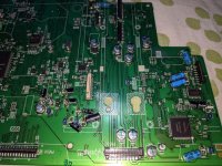
I do not have a meter that reads capacitance; therefore I’m relying on the caps’ labeling to order identical new SMD caps. I assume that the “middle” value on these RCD-W3 caps (such as “47”) represents the capacitance value in MICRO-farads, but when I consulted an online “capacitor guide”, it stated that if there is no symbol after the capacitance value, then the default is PICO-farad.
In the attached picture from the RCD-W3 board, I assume that these 3 caps are marked such that the “V” is “voltage”; therefore I need to find two 100 micro-farad/16 volt SMD caps, and one 220 micro-farad/ 6 volt cap. Correct?

And thank you for the quick response!
I do not have a meter that reads capacitance; therefore I’m relying on the caps’ labeling to order identical new SMD caps. I assume that the “middle” value on these RCD-W3 caps (such as “47”) represents the capacitance value in MICRO-farads, but when I consulted an online “capacitor guide”, it stated that if there is no symbol after the capacitance value, then the default is PICO-farad.
In the attached picture from the RCD-W3 board, I assume that these 3 caps are marked such that the “V” is “voltage”; therefore I need to find two 100 micro-farad/16 volt SMD caps, and one 220 micro-farad/ 6 volt cap. Correct?
Of course you can replace 220uF 6.3V with a higher voltage cap. The V rating is the absolute maximum value the cap can work with before failing. So, you can go higher in V but not higher or lower in Capacitance.
Keep in mind that you need to make sure that after the recap the optical drives will be able to fit on the board without the replacement caps getting in the way
Keep in mind that you need to make sure that after the recap the optical drives will be able to fit on the board without the replacement caps getting in the way
Thanks again, but I think you misinterpreted my question. I have already been searching online for the replacement SMD electrolytic caps, and noticed that none show a “V” for “voltage”, or indicate whether the cap values are measured in “pico” or “micro” farad. But the caps on this Sony unit do have a “V” after “6”, “16”, etc. I just wanted to be certain that my assumptions are correct: (1) the “V” represents “Voltage”, and (2) the capacitance value, such as “47” is measured in “micro” farads.
I’ll assume that I was correct!
Cheers …. John
I’ll assume that I was correct!
Cheers …. John
- Home
- Source & Line
- Digital Source
- Sony RCD-W3 Deck A (Playback only) not playing CDs (Disk Error) repair