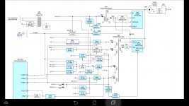
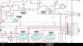
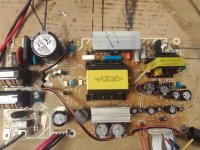
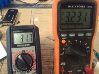
I have a Sony 07dav-13-mp-1-872-105-13(pic 1), that I know is functional, but I don't know how to get it to come out of standby mode. From a Sony manual for a simmilar board, I think I need to apply some voltage (pic 2) to p.cont 1 and/or p.cont 2 / p.cont 3, maybe 5v, but when I tried jumping some of the voltages from the pins, no voltage from the main 31.5V output...yet, anyway.
Does anyone have any knowledge/skill with these? I'd love to get this working for my next project!
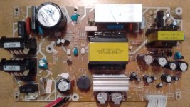
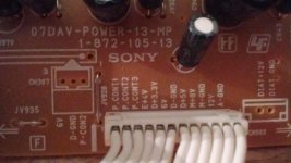
Does anyone have any knowledge/skill with these? I'd love to get this working for my next project!


A full Sony schematic is what you need, but there appears to be a relay
at the top of the board, also what looks to be white optocouplers
I would look up those actual part numbers to see what they are.
If it is a relay, then triggering the coil with an an external 5v voltage source
will give some indication of what the relays function is. The white optocouplers if
that is what they are, similarly will turn on with a trigger voltage, and without
any other info they are likely to be similar to a led ie anode and cathode and
on their output side a transistor or just a variable resistance like a h11f1m.
Hope that helps
Cheers / Chris
The opto's appear to be across the galvanic isolation of the board (primary live mains side to isolated secondary side) and are most likely used for voltage regulation feedback, and perhaps feedback when the PSU is in standby and possible running in a burst mode to save power.
You need to be very very careful in working on these as all the circuitry on the primary side is connected to raw mains.
You need to be very very careful in working on these as all the circuitry on the primary side is connected to raw mains.
Thanks for the replies, this does help! On your advise, I have found the schematic! Ha-Ha!
Here's two screenshots;
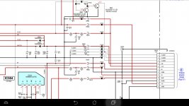
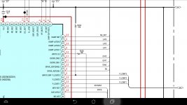
It looks like p.cont1 goes to 3.3V through a 100ohm resistor (R578),
p.cont2 goes to 3.3V, maybe through 1Kohm in a couple places, and,
p.cont3 goes to ground through a 10kohm resistor (R559)
I didn't have too much time, so I grounded 3, and put 3.3V to 1 and 2, and got 31.5V output! but then it slowly dropped to zero again...but progress, anyway
Here's two screenshots;


It looks like p.cont1 goes to 3.3V through a 100ohm resistor (R578),
p.cont2 goes to 3.3V, maybe through 1Kohm in a couple places, and,
p.cont3 goes to ground through a 10kohm resistor (R559)
I didn't have too much time, so I grounded 3, and put 3.3V to 1 and 2, and got 31.5V output! but then it slowly dropped to zero again...but progress, anyway
Can't really tell off that. P_cont2 looks to enable the 5 volt regulator, and also something unseen to the left.
The 10k on P_cont3 looks to be a pull up resistor for the uP output. The uP appears to control the 3 data lines and they all appear to be outputs from the uP (based on what I can see).
The 10k on P_cont3 looks to be a pull up resistor for the uP output. The uP appears to control the 3 data lines and they all appear to be outputs from the uP (based on what I can see).
mmm...I see what you mean about the pullup and regulator. That line to the left just goes to <54> and into the uP. I have the whole pdf document, but it's 6.3Mb, so not sure if I can attach something that big here, but it's the Sony service manual for the HCD-DZ230/DZ231/HD235 I found online. I am not sure if p.cont1 and/or p.cont2 need steady 3.3V or some pulse signal...
You are just going to have to experiment I'm afraid although its not normal for power control signals to be pulsed, they are usually steady. Some SMPS also don't run correctly with out a minimum load being applied... not saying that is the case here but it is something to consider.
Outstanding! Thanks for that info, knowing that it shoud no be some crazy pulse is a big help. I'll try a load and see if that's it, which would make sense, the way it showed voltage then dropped, probably as the cap discharged. I'll post the solution when I get it!
Thanks
Thanks
All those control lines appear to be used to enable/disable various switched supplies in the unit. Having all three enabled at once looks valid so try it.
K, so pouring over the schematics, I found I needed an external 3.3V regulator and a couple resistors, since the 3.3V this board outputs is controlled by a 3.1V external. Did that, now showing 3.1V where it should, all the minor voltages, 3.3, 4, 5, 6, 8, and 12V are all live and regualted appropriately - but still no luck with the 31.5V main. I'm starting to wonder if something is burned out somewhere. I'll keep looking for a while. Was interesting , either way though.
The 31 volts looks like it needs the all time 4 volts on PC903 and a control voltage on Q943/947.
Hard to say what is going on really.
Hard to say what is going on really.
i done this on sony pwb with stk module from micro component system.
you need:
3.3v reg
5v reg
12unreg
12vunreg is powering relay but you need 5v to power protection part of board,3.3v i dont remember why it was and didnt test without it could probably work without.
you can power 5vreg from 12v and 3.3v from 5v.
other connections simply omit.
i used fixed regulators for simplicity and isolated tab and mounted them on same heatsink as stk.
will try to find pictures later as i given that amplifier to friend.
Yes, exactly what I am thinking. I have 3.1V on Q943, and I think the other voltages are where they should be as well, but I see what you mean about the power protection circuits. Last night I wsa looking at the ground paths, and maybe since I have it out of the case, I have inadvertently removed a ground path between the two sides of the supply, so I'm going to try jumpering it where the case would be and see if it is the problem.
- Status
- Not open for further replies.
- Home
- Amplifiers
- Power Supplies
- Sony Power Board Question - How do I turn it on?...
 that's good.