on pin23 of IC-201 shows 1Hz. when I unwillingly shorted pin23 with pin24 the motor stops spinning. motor stands still.I have switch off the CDP and whenn I switch on the CDP the motor spins again.
That suggests the problem could well be related to the RFCK signal not being present. I'll have to look at the circuit later (haven't got it on this laptop). Try tracing that signal back to its source which I think is another processor.
well, I have tryied to wath the signal and RFCK signal is on pin9 of IC-503 there is 0V and 1Hz then goes straight to the pin16 of IC-504 and there is 0V and 1Hz too.
there is one I thing testing connector CNP-27 open with RCFK signal - 0V , 1Hz
there is one I thing testing connector CNP-27 open with RCFK signal - 0V , 1Hz
Its looking like a problem with or around IC503. The master clock is running (you checked with the freq meter). RFCK 1/4 is the signal divided down in frequency by four but the main RFCK is missing to begin with.
Worth checking pins 38 and 39 as its possible a problem there could inhibit something internally within the IC.
In fact its always worth going round any IC and seeing if any other voltages are amiss but its looking a bit like the IC is faulty at the moment.
Worth checking pins 38 and 39 as its possible a problem there could inhibit something internally within the IC.
In fact its always worth going round any IC and seeing if any other voltages are amiss but its looking a bit like the IC is faulty at the moment.
today I have changed complete audio amp board where the IC-503 is located from another CDP which has some different fault (do not read discs, but spindle motor is OK) and the result is OK. motor does not spinns, it is OK so the problem was on the audio amp board.
but I have anotherproblem, CDP does not read the discs as the other CDP. this one was able to read the CDs and now is not. I wonder why, I thouhgt reading (tracking,focusing and moving tray) makes on servo amp board ICs 204,304...
whoaaa it never ends
but I have anotherproblem, CDP does not read the discs as the other CDP. this one was able to read the CDs and now is not. I wonder why, I thouhgt reading (tracking,focusing and moving tray) makes on servo amp board ICs 204,304...
whoaaa it never ends
The laser pick-up connects to the audio amp board, you may have noticed. This is shown on the circuit diagram of the servo amp board as "audio amp board 1/2".
Tracking balance and offset, and focus bias, are adjusted on that section of the audio amp board. They may need re-adjustment for the different pick-up, but you don't have a 'scope.
You could swap the boards back again and swap ic503, but it might be easier to fix the other machine.
Tracking balance and offset, and focus bias, are adjusted on that section of the audio amp board. They may need re-adjustment for the different pick-up, but you don't have a 'scope.
You could swap the boards back again and swap ic503, but it might be easier to fix the other machine.
Last edited:
aah, ofcourse Ive got it 🙂
the fact ist I am not such a technician as most of you (that is the reason I am asking may be stupid questions for you) and I do not have special equipment. for this kind of IC it is for me risk to swap it.
well, I need to buy some required equipment or new CDP.
anyway, thank you very much for help
the fact ist I am not such a technician as most of you (that is the reason I am asking may be stupid questions for you) and I do not have special equipment. for this kind of IC it is for me risk to swap it.
well, I need to buy some required equipment or new CDP.
anyway, thank you very much for help
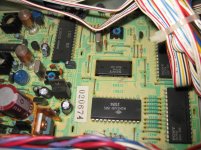
I can't make the package type out from the scanned manual. I take it that it is an SMD (surface mount) package.
Easy... once you have a bit of experience 🙂
Use solder braid to remove most of the solder first and then jewellers screwdriver to gently lift each leg as it is heated with the iron.
Its a bit different to this but you get the idea,
http://www.diyaudio.com/forums/parts/127924-working-smd-how-do-without-specialised-tools.html
Use solder braid to remove most of the solder first and then jewellers screwdriver to gently lift each leg as it is heated with the iron.
Its a bit different to this but you get the idea,
http://www.diyaudio.com/forums/parts/127924-working-smd-how-do-without-specialised-tools.html
nice manual, looks easy. well, I will try it. unfortunately no time for this yet, but I must to do it. nothing to loose 🙂
thank you
thank you
Sorry, not ignoring your post 🙂 I'd have to study the circuit again... as nothing obvious came to mind.
hello,
you do not have to apologize. today I have placed the "wrong" IC-503 to the other board where I get the "good" IC-503 and this board is working good (spindle motor is not spinning without reason) so I am sure the IC-503 was OK.
you do not have to apologize. today I have placed the "wrong" IC-503 to the other board where I get the "good" IC-503 and this board is working good (spindle motor is not spinning without reason) so I am sure the IC-503 was OK.
- Status
- Not open for further replies.
- Home
- Source & Line
- Digital Source
- Sony CDP-101 spindle motor