I got this Amp, repaired allready from somebody Else. Problem is a loud Pop on and Office noise. If i connect The oscilloscope directly to the speaker Terminals, it shows that the Amplitude is more on the negativ side. If i switch remote off, the voltage Drops from - 13 volt to Zero.. What Can this cause?
Attachments
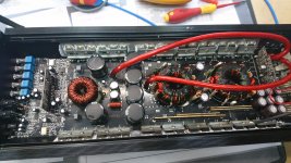
Found, that on one side, i have no full Amplitude for high and low... I have to check, what is it pulling down.
Again... so the amp produce audio very well, but when i connect remote, i have a loud bump. If i disconnect the remote, again a bump, but not so loud. If i connect the osci to the audio outputs, without any other load, and give a 100Hz sine inside, the carrier is a little bit below the center line to the negative. If i switch of the amp, i got -13VDC, which are very quick going to 0V. It looks to me like a class 5 amp, because the 100V caps are in line and not parallel. I have only positive at the fets.
Could my problem also happen, if an Audio op-amp is leaking, and always is below 0V? The Amp, what i can see has only 3pcs. 7805 Voltage regulators....
Could my problem also happen, if an Audio op-amp is leaking, and always is below 0V? The Amp, what i can see has only 3pcs. 7805 Voltage regulators....
i dont know, on which pin i have to look. I just tested again with a multimeter on the outputs. No audio input. The output slowly going to 1,5V - DC offset.... If i remove remote, the voltage drops to minus 30V and in about 4seconds, its at 0V with no load connected. So i dont think, it comes from the mute circuit.
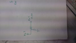
Looking at the component side of the audio driver board, it's pin 3. Pin 2 is ground. Pin 4 is -15v.
On the first three Pins is Zero volt. PIN 4 - 12v,PIN 5+12v,then Amplitude for outputs. Ground is b-
could it also be possible, that one output fet is leaking? Because i think, if i remove remote, the gates are directly off, so the mosfets should not fed anymore the output. But it still need a few seconds, before the dc on the output terminal reaches 0V???
The mute line is supposed to be high, initially and after a short delay, drop to 0v. If it's always 0v, it's not switching the driver board off and allowing the pop. There may be other problems but this is the first thing to check.
The amp should be similar to the SLA1500. Check Q21/22.
http://www.bcae1.com/temp/SLA1500.pdf
The amp should be similar to the SLA1500. Check Q21/22.
http://www.bcae1.com/temp/SLA1500.pdf
I was looking for that circuit, but Can not found. All Transistors are ok. If iam right, on the audio drive Board is an ir21844s. PIN 2 for shutdown ist going on an 8 PIN ic, probably an tl074??? So the delay is generated on the audio drive Board?
Maybe this will help to locate the Problem??ß
Pin 1: 0,1V
Pin 2: 0V
Pin 3: 0V
Pin 4: -11,8V
Pin 5: +11,89V
Pin 6: 2,4V Squarewave
Pin 7: 2,4V Square Wave
Pin 8: 0V
Pin 9: +5V
Pin 10: 2,3V Squarewave
Pin 11: 2,3V Squarewave
Ground on Bat -
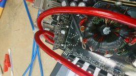
For starting, the squarewave on the Fets starts building, when the red light goes off, and it switches to blue light. So, there are 1-2 seconds, before building up waves on the output.
Pin 1: 0,1V
Pin 2: 0V
Pin 3: 0V
Pin 4: -11,8V
Pin 5: +11,89V
Pin 6: 2,4V Squarewave
Pin 7: 2,4V Square Wave
Pin 8: 0V
Pin 9: +5V
Pin 10: 2,3V Squarewave
Pin 11: 2,3V Squarewave
Ground on Bat -
For starting, the squarewave on the Fets starts building, when the red light goes off, and it switches to blue light. So, there are 1-2 seconds, before building up waves on the output.
Attachments

Last edited:
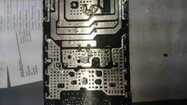
Are you saying that there is no trace on the main board (top or bottom) leading away from that pin?
On the PS drive board, this pin is connected to a transistor, marked M6. The two pins in a row on that transistor have +12V, during start up, there is a square wave on the first pin. The single pin of that transistor is connected to pin 3. So maybe this is the circuit for mute? Could the transistor a KST812?
ah, wait...i found a datasheet for M6--should be a KST812M. According that, the diode, or the Pin 3 from the audio drive board is connected on collector of that transistor. Emitter has always 12V, Base got 12V during start up and stay on all the time....but nothing on the collector...
Virtually any PNP transistor with the same package type will work.
Are those pins shorted together?
The emitter is connected to the 12v supply. The base should be about 1/2v below the emitter on startup. After a short delay, the base should be pulled up to the emitter voltage.
Are those pins shorted together?
The emitter is connected to the 12v supply. The base should be about 1/2v below the emitter on startup. After a short delay, the base should be pulled up to the emitter voltage.
- Status
- Not open for further replies.
- Home
- General Interest
- Car Audio
- Sonido Mask 2000.1