Came across this and just wondering what people might think of a little more serious effort on this?
https://maker.pro/analog/projects/diy-simple-gu81-tube-hybrid-amplifier-130-watts-rms-in-a-class

https://maker.pro/analog/projects/diy-simple-gu81-tube-hybrid-amplifier-130-watts-rms-in-a-class
Several corners cut there to get sound out of the big tube, but could be a basis for a working amp, yes.
The biggest problem is getting a good SE OPT for these power levels. https://www.monolithmagnetics.com/s...33 single ended output transformer prelim.pdf is one I know that can do the 130W (@ 35Hz), costs 2000 euros each, add VAT to that.
Ah, I do not understand why G2 is connected to the cathode...
I made a GM70 SE amplifier which operates at half the B+, but the principles could apply to the amp above.
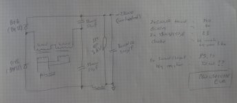
Using of microwave PT. One could maybe find two equal ones and share the load, but I would look for industrial power transformer with 400V secondaries, connect two of these in series (for 800V on the secondary) and feed it into a voltage doubler. I used a single PT, so 400V into the doubler. https://sklep.toroidy.pl/en_US/p/STS0500-Transformer-TS-500VA-400230V/142
The voltage doubler would be made of two diodes of this series https://www.tme.eu/Document/88eb08765dfdbcb7fde87e4b3c72eaf5/by4.pdf and two DC-link caps at circa 1300V, say 50uF, something like this https://www.digikey.ch/de/products/detail/epcos-tdk-electronics/B32320I1506K000/13914403
A choke goes in the negative side of the output. This way, the voltage difference between the winding and the core is kept in a safe range. After the choke a cap rated for full B+ (which will be about 2,3kV in idle), something like this https://www.digikey.ch/de/products/detail/epcos-tdk-electronics/B25690A3107K003/16836406 Find some high value resistor (1M??) rated for high voltage to connect as bleeder.
To connect everything, use some prototype board without any copper, I used something similar to this https://www.digikey.ch/de/products/detail/vector-electronics/64P44WE/38933 Make tight mechanical connections between components, and only then use solder to ensure lasting electrical contact.
I avoided series connection of smaller diodes because making them share the voltage equally requires more components, so more connections that can go wrong. Connecting the caps in series can also work, but again, more connections and if one of the resistors gets disconnected the voltage balance over the caps is not assured. I also suspect that 470k are too small for equal voltage sharing - the current through the resistor must be (much) larger than the leaskage current of the caps. Caps with high capacity and voltage have quite a leakage. In the example below it is: I(uA) = 3*sqrt(C*V), so 3*sqert(820*400) = 1718uA, or almost 2mA. Say the bleeder must pass 5mA, each bleeding resistor must be around 80k. The whole string would produce about 10W of heat (2000V*5mA), which is never nice around caps.
https://www.chemi-con.co.jp/products/relatedfiles/capacitor/catalog/SMQN-e.PDF
A PS like this, using 2x 500VA PT would cost around 300 USD/EUR/CHF, much less than the OPT.
The biggest problem is getting a good SE OPT for these power levels. https://www.monolithmagnetics.com/s...33 single ended output transformer prelim.pdf is one I know that can do the 130W (@ 35Hz), costs 2000 euros each, add VAT to that.
Ah, I do not understand why G2 is connected to the cathode...
I made a GM70 SE amplifier which operates at half the B+, but the principles could apply to the amp above.
Using of microwave PT. One could maybe find two equal ones and share the load, but I would look for industrial power transformer with 400V secondaries, connect two of these in series (for 800V on the secondary) and feed it into a voltage doubler. I used a single PT, so 400V into the doubler. https://sklep.toroidy.pl/en_US/p/STS0500-Transformer-TS-500VA-400230V/142
The voltage doubler would be made of two diodes of this series https://www.tme.eu/Document/88eb08765dfdbcb7fde87e4b3c72eaf5/by4.pdf and two DC-link caps at circa 1300V, say 50uF, something like this https://www.digikey.ch/de/products/detail/epcos-tdk-electronics/B32320I1506K000/13914403
A choke goes in the negative side of the output. This way, the voltage difference between the winding and the core is kept in a safe range. After the choke a cap rated for full B+ (which will be about 2,3kV in idle), something like this https://www.digikey.ch/de/products/detail/epcos-tdk-electronics/B25690A3107K003/16836406 Find some high value resistor (1M??) rated for high voltage to connect as bleeder.
To connect everything, use some prototype board without any copper, I used something similar to this https://www.digikey.ch/de/products/detail/vector-electronics/64P44WE/38933 Make tight mechanical connections between components, and only then use solder to ensure lasting electrical contact.
I avoided series connection of smaller diodes because making them share the voltage equally requires more components, so more connections that can go wrong. Connecting the caps in series can also work, but again, more connections and if one of the resistors gets disconnected the voltage balance over the caps is not assured. I also suspect that 470k are too small for equal voltage sharing - the current through the resistor must be (much) larger than the leaskage current of the caps. Caps with high capacity and voltage have quite a leakage. In the example below it is: I(uA) = 3*sqrt(C*V), so 3*sqert(820*400) = 1718uA, or almost 2mA. Say the bleeder must pass 5mA, each bleeding resistor must be around 80k. The whole string would produce about 10W of heat (2000V*5mA), which is never nice around caps.
https://www.chemi-con.co.jp/products/relatedfiles/capacitor/catalog/SMQN-e.PDF
A PS like this, using 2x 500VA PT would cost around 300 USD/EUR/CHF, much less than the OPT.
Attachments
Indeed, in the test, he uses a dynacord 50W. I am almost sure it is a PP transformer, that is unable to take the standing DC and also the voltage levels present in a 2.3kV amp. As I mentioned, it will make sound, but that is it, but worse, using this OPT under such conditions is very dangerous (I am thinking about corona discharges, etc).
The more I read the worse it gets. Microwave transformers not rated for 100% duty cycle? Wire two in series of course. Kilovolts on an old output transformer not rated SE operation? Slap that bad boy in. Can the GU81 even operate with zero bias?

Correction: .... Into a hi-fi tube amplifier"I think the next step will be: "how to transform an inverter welding machine into a hi-fi amplifier".
😀
Been there, Built that........or something similar to it about 20 years ago.
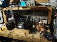
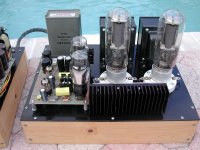
The first picture shows a glowing 833A tube.
They are fine at zero bias providing the plate voltage keeps the dissipation under control. Voltage here was about 1500 volts and the optimum current was 270 mA. A slight negative bias was needed to keep the tube dissipation to about 400 watts. More current did not improve performance, but less did cause a loss of power output.
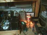
The power supply for this test was removed from a discarded vacuum tube Motorola base station for ambulance dispatch. It had a SOLA constant voltage transformer on it that weighed about 60 pounds, seen on the left side of the picture.
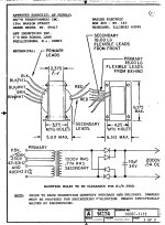
The OPT was custom built for this purpose by Transcendar about 20 years ago. The cost back then was about $300. It was designed for 5000 ohms to 0-4-8 at 200 watts, seen on the right side of the picture. I used the mosfet driver board on my 845 / 211 SE amp to drive the 833A. It is similar to the PowerDrive circuit I use in most of my amplifiers but made with larger parts and mounted on a heatsink. It is on the left side of the empty 845 sockets on the amp chassis. The actual driver tubes are 45s on an original TSE board on the amp chassis behind the PowerDrive board and the 845 sockets.
The big brown resistor in front of the OPT is a 500 watt 8 ohm load. It got HOT! Power output at the edge of clipping (5% THD) is just over 200 watts at 1 KHz.
Note that this was a test circuit to verify the operation of the OPT and was NOT constructed for use by anyone other than me as it is definitely NOT safe! It existed for one week only, then it was disassembled. Note that the yellow Radio Shack clip lead carries the 1500 volt B+ from the power supply to the "monster cap" which came from a cardiac defibrillator. The tube socket consists of hose clamps and Vice Grips.
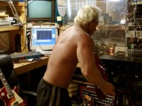
Other than when pictures were being taken, there was a 1/4 inch thick Lexan "blast shield" between me and this thing and a fire extinguisher at my feet. I must say that it survived some of the worst case test conditions that it could have been subjected to, my guitar playing. The only "occurrences" were that the 15 amp bench breaker got tripped twice. A picture of me abusing this thing with a Les Paul has been my avatar for years.
The third picture shows the obviously dated setup (CRT TV and computer monitors). The amp is being driven by an ADA MP1 MIDI controlled guitar preamp (black rack mount unit between me and the Les Paul). I'm using a preset that I named JIMI to drive everything well beyond normal operation, then to wreck havoc I'm holding a Stratocaster up in front of the speaker to create acoustical feedback while holding a chord on the fretboard. Not the plethora of spikes in the FFT on the PC screen, still it sounded pretty good though.
Could this have been transformed into a "HiFi" amp? Maybe. That was the original intention back before Tubelab Inc. even got off the ground. The Sola transformer did what all Solas do, buzz and get hot, so I got a suitable quiet power transformer from a 500 watt Harris radio transmitter, but never built anything with any of this stuff. Transcendar doesn't exist now, so a second OPT would be hard to get and I don't need a 200 watt SE guitar amp......but it would be cool..... or maybe HOT!
Anyone want the two transformers and a few 833As?
The first picture shows a glowing 833A tube.
They are fine at zero bias providing the plate voltage keeps the dissipation under control. Voltage here was about 1500 volts and the optimum current was 270 mA. A slight negative bias was needed to keep the tube dissipation to about 400 watts. More current did not improve performance, but less did cause a loss of power output.
The power supply for this test was removed from a discarded vacuum tube Motorola base station for ambulance dispatch. It had a SOLA constant voltage transformer on it that weighed about 60 pounds, seen on the left side of the picture.
The OPT was custom built for this purpose by Transcendar about 20 years ago. The cost back then was about $300. It was designed for 5000 ohms to 0-4-8 at 200 watts, seen on the right side of the picture. I used the mosfet driver board on my 845 / 211 SE amp to drive the 833A. It is similar to the PowerDrive circuit I use in most of my amplifiers but made with larger parts and mounted on a heatsink. It is on the left side of the empty 845 sockets on the amp chassis. The actual driver tubes are 45s on an original TSE board on the amp chassis behind the PowerDrive board and the 845 sockets.
The big brown resistor in front of the OPT is a 500 watt 8 ohm load. It got HOT! Power output at the edge of clipping (5% THD) is just over 200 watts at 1 KHz.
Note that this was a test circuit to verify the operation of the OPT and was NOT constructed for use by anyone other than me as it is definitely NOT safe! It existed for one week only, then it was disassembled. Note that the yellow Radio Shack clip lead carries the 1500 volt B+ from the power supply to the "monster cap" which came from a cardiac defibrillator. The tube socket consists of hose clamps and Vice Grips.
Other than when pictures were being taken, there was a 1/4 inch thick Lexan "blast shield" between me and this thing and a fire extinguisher at my feet. I must say that it survived some of the worst case test conditions that it could have been subjected to, my guitar playing. The only "occurrences" were that the 15 amp bench breaker got tripped twice. A picture of me abusing this thing with a Les Paul has been my avatar for years.
The third picture shows the obviously dated setup (CRT TV and computer monitors). The amp is being driven by an ADA MP1 MIDI controlled guitar preamp (black rack mount unit between me and the Les Paul). I'm using a preset that I named JIMI to drive everything well beyond normal operation, then to wreck havoc I'm holding a Stratocaster up in front of the speaker to create acoustical feedback while holding a chord on the fretboard. Not the plethora of spikes in the FFT on the PC screen, still it sounded pretty good though.
Could this have been transformed into a "HiFi" amp? Maybe. That was the original intention back before Tubelab Inc. even got off the ground. The Sola transformer did what all Solas do, buzz and get hot, so I got a suitable quiet power transformer from a 500 watt Harris radio transmitter, but never built anything with any of this stuff. Transcendar doesn't exist now, so a second OPT would be hard to get and I don't need a 200 watt SE guitar amp......but it would be cool..... or maybe HOT!
Anyone want the two transformers and a few 833As?
Attachments

Seriously, it would be possible to build an amplifier in this manner, but it would take a LOT more serious effort, a LOT of money, and some experience in building electronics that will see peak voltages in the 3KV+ range!Came across this and just wondering what people might think of a little more serious effort on this?
As stated by other posters and the original author, a real OPT that was intended for use in a Single Ended amp at a high power and voltage level is required for safety and undistorted sound. A push pull transformer will experience saturation from the DC current. If the author ever tried to listen to music through decent speakers at more than a few watts with any bass response at all, he would have heard serious distortion.
Other than the one off oddball that I have, you would be looking at the Hammond 1642SE which costs around $375 each plus shipping for about 20 pounds each. There are other semi custom OPTs available for far more money. Depending on the choice of tube and the desired power output level this will also be a large and expensive transformer. The 1642SE OPT is rated for 75 watts of power. This could be pushed a bit if you didn't pound it with a lot of bass. The OPT will see peak voltages near twice the B+ voltage, and even more if the amp is pushed into clipping into an inductive load like a speaker.
Then you would need a serious SAFE power transformer capable of providing plate power to a pair of large output tubes. The HV winding on a microwave oven transformer is grounded at one end which precludes the use of a bridge rectifier. Yes, it can be cut loose, but the entire winding was NOT intended to float at a high voltage level that would be seen in a bridge rectifier setup. A class A2 SE amp can reach a theoretical maximum of 50% efficiency, so to get 150 watts of audio power (75WPC) you will need a minimum of 300 watts of DC power.
Reality says that you will never get 50% efficiency, and likely see 20 to 30% with a tube capable of high peak currents like the 833A that I used. This means that you will need somewhere between 500 and 750 watts of DC power. This will likely be something in the 17.7 pound range from the Hammond 700 series or similar. Price, around $500. You will also need a transformer or SMPS to power the 100 watt or larger filaments in teach output tube.
I taught myself electronics at a young age in the days when consumer electronics used vacuum tubes. I started working in electronics repair from age 15 but got a job at Motorola at age 20 in 1973 where everything used transistors. Vacuum tubes faded into a dark corner of my brain except for a few guitar amp repairs or builds. Sometime in the early 90's I got over 100,000 vacuum tubes in exchange for a few weekends of work cleaning out an abandoned warehouse where they had been stored since the 1950's.
Details in posts 7 and 8 here if interested:
https://www.diyaudio.com/community/...entode-g3-tied-to-heater.402939/#post-7446098
There were lots of large transmitting tubes in that lot including 811As, 813s, 211s, 845's and the big boy 833As. I built the 845SE amp that is seen in the photos and set out to build a bigger amp using the 833A tubes. That's why I had one custom OPT made. Common sense took over as I realized that I didn't really need or want the 30 WPC that I got from the 845 amp. I could only listen to it for 1 to 2 hours since the 500 watts of heat it put into my 10 X 10 foot room made it unbearably hot. I didn't really want to build a 1 KW room heater. I also realized that high voltage transmitting tubes want a high impedance OPT. A high impedance OPT that can handle 1KV+ voltages will be expensive. It is possible to make similar power levels with 2 or 3 small TV sweep tubes in parallel on 500 volts or so with more budget friendly OPT's and a lot less heat.
I don't know your experience level, but as with all DIY projects, the probability of success goes down as the envelope gets pushed closer to the edge. As I learned with automobile engines, many backyard mechanics can squeeze 300 HP from an old small block Chevy engine. How many backyard builds at the 500+ HP level live beyond the first trip down the track. That's why I got a lot of help (and expensive parts) from a man named Shelby when I wanted to beat 5.0L Mustangs with a 2.2L 4 cylinder Dodge in the mid 1980's.
I tell tube amp builders the same thing. Do not start with a high power build that is above what's common for a first project. You will usually wind up with some expensive burnt parts. The power level for a high probability of first project success is about 10 watts for an SE amp and maybe 30 to 50 watts for a push pull amp.
Building a 5 to 15 watt SE amp is pretty much a given for most builders. Build or copy a Tubelab SSE. Want 30 watts of SE power? There are several 211A or 845 amps running at this power level, but they take a lot more attention to detail at the 1KV+ voltage level than an SSE at 460 volts. Power levels above 30 watts in an SE tube amp are not common, but can be done. they are not suitable for a first project though.
Attachments

- Home
- Amplifiers
- Tubes / Valves
- Something interesting Class A hybrid