PDF for the driver: http://www.p-audio.co.uk/pdf/SD21_1800N.pdf
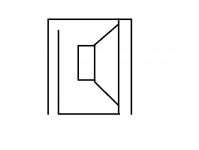
I'm working on a compact cabinet for one of these, to be used as part of my PA system. In order to minimise frontal area, I've tried simulating the cabinet where the driver fires out of a pair of slots, one of the slots is in front of the driver, the other being the BR port - see attachments.
With modern music reaching into the 30s, I'd like a cabinet that can reach those frequencies without straining, and also go loud enough for outdoor events for a couple of hundred people. I'm fairly sure this design achieves this, though would appreciate some feedback there. My concern is that the cone may be very unevenly loaded by firing out of that small slot at the top end. Some PPSL designs work in a similar way, with no failures reported, so I suspect it'll be okay.
Bracing such a large panel in front of the driver may prove difficult, though strengthening ribs ought to help. That panel will be removable, though, so that the driver can be mounted.
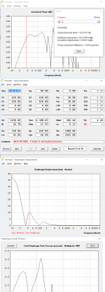
The side cross-section would be a 60x60cm square, with a pair of full-height 7cm slots. Vent velocity peaks around 19m/s on the sims.
HR sims attached, 80v input used to keep within Xmax, which leaves a bit of wiggle room to EQ the response flat. I'll be using a C.Audio RA3001 bridged, which can put out 100v rms, so there's a bit of headroom there.
I also have a set of four 15" subwoofers that match the output of this design well in the 50-35Hz range, so will be using the 4x15"s at one side and this cabinet at the other. Tops are currently a pair of 12" two-way cabs, to be replaced with some 2x10 tops. Crossover around 100Hz.
Chris
I'm working on a compact cabinet for one of these, to be used as part of my PA system. In order to minimise frontal area, I've tried simulating the cabinet where the driver fires out of a pair of slots, one of the slots is in front of the driver, the other being the BR port - see attachments.
With modern music reaching into the 30s, I'd like a cabinet that can reach those frequencies without straining, and also go loud enough for outdoor events for a couple of hundred people. I'm fairly sure this design achieves this, though would appreciate some feedback there. My concern is that the cone may be very unevenly loaded by firing out of that small slot at the top end. Some PPSL designs work in a similar way, with no failures reported, so I suspect it'll be okay.
Bracing such a large panel in front of the driver may prove difficult, though strengthening ribs ought to help. That panel will be removable, though, so that the driver can be mounted.
The side cross-section would be a 60x60cm square, with a pair of full-height 7cm slots. Vent velocity peaks around 19m/s on the sims.
HR sims attached, 80v input used to keep within Xmax, which leaves a bit of wiggle room to EQ the response flat. I'll be using a C.Audio RA3001 bridged, which can put out 100v rms, so there's a bit of headroom there.
I also have a set of four 15" subwoofers that match the output of this design well in the 50-35Hz range, so will be using the 4x15"s at one side and this cabinet at the other. Tops are currently a pair of 12" two-way cabs, to be replaced with some 2x10 tops. Crossover around 100Hz.
Chris
Attachments
i might aim to make the slot it's firing into a bit larger to reduce the possibility of compression issues.
came across a site a while back of a company that only does subs with reflector panels, albeit open on all sides.
came across a site a while back of a company that only does subs with reflector panels, albeit open on all sides.
Bracing such a large panel in front of the driver may prove difficult, though strengthening ribs ought to help. That panel will be removable, though, so that the driver can be mounted.
I think you might run into some problems trying to both effectively brace that panel AND make it removable. That was one of the main failings of my POC2 design.
i might aim to make the slot it's firing into a bit larger to reduce the possibility of compression issues.
came across a site a while back of a company that only does subs with reflector panels, albeit open on all sides.
The outlet velocity of the slot comes in at just over 15m/s at 80v drive at 50Hz. I think that'll be okay. The bass reflex port goes a little higher (around 19m/s IIRC), but still not too bad. There are lots of conflicting rules of thumb on vent velocity, but I usually aim for <20m/s.
I think you might run into some problems trying to both effectively brace that panel AND make it removable. That was one of the main failings of my POC2 design.
Hi Brian,
I was thinking of doing something like this:

On the inside of the panel. I would hope that gluing some plywood on the inside (while avoiding where the cone might hit) would stop the panel from 'breathing' in and out with the pressure.
Chris
The outlet velocity of the slot comes in at just over 15m/s at 80v drive at 50Hz. I think that'll be okay. The bass reflex port goes a little higher (around 19m/s IIRC), but still not too bad. There are lots of conflicting rules of thumb on vent velocity, but I usually aim for <20m/s.
Hi Brian,
I was thinking of doing something like this:
On the inside of the panel. I would hope that gluing some plywood on the inside (while avoiding where the cone might hit) would stop the panel from 'breathing' in and out with the pressure.
Chris
i wouldnt be so much worried about the vent velocity but rather the actual compression on the cone of the driver. if im looking at your hornresp sim correctly it seems that the reflector panel/space etc is roughly a quarter of sd, this might or might not present an issue during long term playback. something to look at anyway.
the plywood ribbing will help and doubling up that panel would stiffen it as well. again, very high impact/energy area. my ms paint skills are awful and describing it may not make sense, but if you were to use an arching rib whose legs hung over at the ends (down in the outlet cavity), you could use a fastener from the cabinet into the brace as well.
im interested to see how it turns out.
The Xmax on the SD21-1800N is 14 mm according to the conventional method of adding 1/4 Hg. Optimising the design for 120 V would make more sense. As long as HR says excursion is within 20 mm simulated and your not exclusively playing sinewaves, that will do fine.
Johan
Johan
The driver used in the Orthorn was this one, IIRC: B&C Speakers
Which survived simulated pressures around twice those Hornresp is reporting for this design. This P.Audio driver isn't quite in the same league as the 21SW152, but its not far off. That said, I might err on the side of caution and increase the slot widths.
Not sure what you mean about the ribs - MS paint or even a pencil sketch would be useful 🙂
Edit - Cross-post with Rademakers.
Putting 120v into this design will nudge 130dB in places, which is pretty impressive. I'll run some sine waves through the driver free-air so I can get an idea of when distortion sets in. Port velocity is up at 28m/s, so I'll definitely need to play with that a bit.
Cone pressure stays reasonable - 5500Pa where the Othorn was up over 9000Pa.
Chris
Last edited:
Not sure what you mean about the ribs - MS paint or even a pencil sketch would be useful 🙂
Chris
crude and quick sharpie will surely do. basic side profile of the top, ribbing, like the picture you posted to repeat every 4-6" +/-
will allow fastener down from the top as well as in from the sides.
Attachments

Ah yes, I see what you mean. It might help, though the maximum amplitude of panel flexing occurs at the centre, so the ribs will be thickest there. More surface area to attach to the rest of the cabinet would be useful, so I'll include that where possible.
I've just had the driver on the end of an EP1500 bridged (up to around 900w into this driver), and can report that it'll do around 30mm p/p travel before the knocking sound of a stretched suspension becomes obvious. Excursion seems to stop pretty quickly after that - some drivers are pretty gradual, but not this one. Some low-order distortion probably starts creeping in as you go past Xmax, but since I was testing free-air at low frequencies (10-30Hz sine waves, plus some music playback), the distortion components would be low enough in frequency and volume that the dipole losses would render them inaudible here.
Its good to know that even a pretty serious "oops" moment is unlikely to kill this driver mechanically.
There was a lot of wind noise from the motor vents, particularly the pole piece vent, so some lining of the BR chamber might be necessary to kill those off. Wind noises started around 10mm p/p and went up from there. The wind noises will probably be masked by the LF output, but since an inch or two of felt won't add much weight, I'll do it anyway.
So...
- bigger amp will yield more output - around 120v looks good, and corresponds exactly to the 1800w thermal rating. Who knew?**
For now, the amp I have will give plenty of output and no worries about excursion.
- ports will need to be bigger, since I'm going from 800w sims to 1800w.
**That said, 120v is more voltage than a bridged RMX2450 will swing, so we're looking at the QSC PLX series, or maybe a Crown XS900. That'd mean spending money when I have quite a lot of this stuff lying around. There's 1.5dB between 120v and 100v, so I might optimise for 100v and call it good, especially when power compression is going to take a chunk out of that 1.5dB.
At 100v input, there's 125dB at 35Hz going up to 128dB at 40Hz and 130dB from 50Hz and up. Not bad.
Chris
Chris,In order to minimise frontal area, I've tried simulating the cabinet where the driver fires out of a pair of slots, one of the slots is in front of the driver, the other being the BR port - see attachments.
According to your sketch, frontal width appears only reduced a few inches compared to a "normal" BR.
Why do you want to minimize frontal area?
Is output sim any better with the slot than if that volume was added to the BR box?
Art
Last edited:
A narrow frontal area would be nice for a couple of reasons...
- less horizontal stage space used in cramped situations
- can be used on its side with a monitor wedge on top
A standard ported box would come out roughly cube-shaped, which I'd like to avoid, since a cube's a cube no matter which way you turn it. It'd be quite nice to just have slots visible - with no visible driver, the output will hopefully be surprising.
I'd probably make the cabinet taller and deeper to keep a reasonably narrow-ish cabinet. Think QSC KSub and you're somewhere near.
Chris
A narrow frontal area would be nice for a couple of reasons...
How narrow are you looking for?
With a 21" driver, you can get as narrow as around 23", using 3/4" ply. That's pretty narrow ...
Hi Brian,
If I used something with a ~23" square front, the cabinet would be approximately 23" deep internally - aiming for around 200L. Cubes are quite difficult to move around, so I'd like to offset the ratio of dimensions a bit.
Chris
If I used something with a ~23" square front, the cabinet would be approximately 23" deep internally - aiming for around 200L. Cubes are quite difficult to move around, so I'd like to offset the ratio of dimensions a bit.
Chris
Hi epa,
Unfortunately the driver hasn't been out of its box much apart from some quick testing - I've been making some 2x10" tops instead, since the old 12" ones were running into serious power compression problems.
I can tell you that, free air, the P-Audio driver will manage 30mm p/p travel before it goes non-linear. Getting it to go much further than that was difficult, even with a bridged EP1500. The extra excusion means it'll probably do well in a low-tuned alignment. I'd like to get 30Hz out of it, but also keep the cabinet small enough for a 1-man lift.
This driver is next up to go into some kind of box, so I'll be updating again in the coming weeks.
Thanks for your interest,
Chris
tnx 4 the update
your design is not bad
it gives u better preformence in the upper range.
the port has to be a bit longer then a normal br.
let us know when you put to the test
your design is not bad
it gives u better preformence in the upper range.
the port has to be a bit longer then a normal br.
let us know when you put to the test
Hi,
Putting a front firing slot in front of a side firing subwoofer
is extremely pointless and does absolutely nothing useful.
IMO just lose the front slot, literally a waste of space.
Sidefiring should make no difference to a subwoofer.
rgds, sreten.
The front slot will also have cavity resonances, which may
or may not be a problem depending on the low pass filter.
Last edited:
i disagree that its pointles.
if you don't want the driver exposed
you also gain output in the upper range
you get some volume back because you dont have to reces the front bafle
youre right about the cav res but not a problem< 100hz
if you don't want the driver exposed
you also gain output in the upper range
you get some volume back because you dont have to reces the front bafle
youre right about the cav res but not a problem< 100hz
i disagree that its pointles.
if you don't want the driver exposed
you also gain output in the upper range
you get some volume back because you dont have to reces the front bafle
youre right about the cav res but not a problem< 100hz
Hi,
You don't gain any output farfield, that is a slot loading myth.
rgds, sreten.

- Status
- Not open for further replies.
- Home
- Loudspeakers
- Subwoofers
- Something big - P-Audio SD21-1800N