Hi People.. 🙂
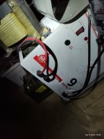
i'm an Audio Freak who has just recently Gotten me a Profile in here, although have read a post now & then for the Last 20-30 years.... i have not gotten around to do some testing Yet, so i just thought i could shoot a post and ask someone in here, if some possibly would know the winding ratio or anything, i was at the Elma TT web site in russia, but for some weird reason i was not able to search in the site...
Anyhow 🙂
May we all Come To Hi-Fi Valhalla in The End.. 🙂
Attachments


Thanx Koda 😎
As i said i just have not gotten around to it yet, so many things to Do..
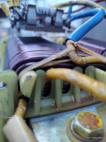
Time Races On, i just thought if someone in here could possibly Own / Have The same transformer and know the Specs on the Fly 😎
Even More frustratingly i found The Russian ELMA TT Web site but could not do anything.??
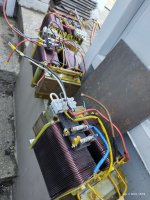
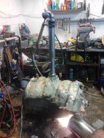
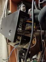
It is from an UPS, from one of the many & Growing industrial company's around the rural area here where i live 🙂
All their EE-Waste Containers Are A Goldmine Of Things Like That...
i Once got hold of some kind of OffShore Inverters / Truck.? chargers and they held 32 Pcs IRFP240 N-Mosfets Each 🙂
And all except 2 or three was in good condition if i remember...
Also i know that the primary is 220v and that the innermost windings usually are the primary's, so i just throw on a series R And Plugg It in if it says bang.!!
i've just gotta reset the fuse,, he he i am suspecting that the fuse has lost it's trip value because i can't count how many times i've tripped it hi hi 🙂
As i said i just have not gotten around to it yet, so many things to Do..
Time Races On, i just thought if someone in here could possibly Own / Have The same transformer and know the Specs on the Fly 😎
Even More frustratingly i found The Russian ELMA TT Web site but could not do anything.??
It is from an UPS, from one of the many & Growing industrial company's around the rural area here where i live 🙂
All their EE-Waste Containers Are A Goldmine Of Things Like That...
i Once got hold of some kind of OffShore Inverters / Truck.? chargers and they held 32 Pcs IRFP240 N-Mosfets Each 🙂
And all except 2 or three was in good condition if i remember...
Also i know that the primary is 220v and that the innermost windings usually are the primary's, so i just throw on a series R And Plugg It in if it says bang.!!
i've just gotta reset the fuse,, he he i am suspecting that the fuse has lost it's trip value because i can't count how many times i've tripped it hi hi 🙂
Attachments
-
 SDC10288.JPG492.4 KB · Views: 78
 -
 SDC10376.JPG444.2 KB · Views: 83
 -
 1927638_49349010964_4141_n.jpg39.4 KB · Views: 102
 -
 21733355_10154810593081606_724339822_n.jpg93.5 KB · Views: 99
 -
 IMG_20170618_184243.jpg595 KB · Views: 75
 -
 IMG_20200910_123443636.jpg326.7 KB · Views: 75
 -
 IMG_20190724_145718_01.jpg291.1 KB · Views: 82
 -
 IMG_20220407_151816766_HDR.jpg488.7 KB · Views: 85
the Elma TT web site in russia, but for some weird reason i was not able to search in the site...
Think "WW3 starting" and then it will make more sense. 🙁Even More frustratingly i found The Russian ELMA TT Web site but could not do anything.??
he He 😎
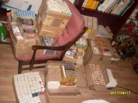
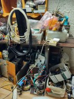
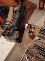
Instead i went amuck with Pictures Not All of them really related to the Iron's in the last Pic.... Cheer's Everybody & All 🙂
Instead i went amuck with Pictures Not All of them really related to the Iron's in the last Pic.... Cheer's Everybody & All 🙂
Hi... JMFahey A very fair and good Point you make.. 😎
Those few minutes earlier i had time to google around. That did not at all hit me then, But It of Coarse makes common sense.... 🙂
Those few minutes earlier i had time to google around. That did not at all hit me then, But It of Coarse makes common sense.... 🙂
Yessa 🙂 A beuty Of xformers they are, any one needin one, i have three and probably wont use the third.... 🙂
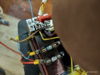
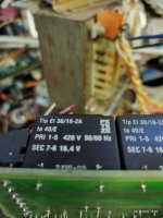
Althoug With a heck of a secondary voltage, of 192 volts, if the dual Coils is seperated, 96 Volts.. 🙂
So as with 209 volts directly on the primary coil's i measured 179 volts on the secondarys,
with witch we divide 209 to 179 volt's to find the Winding RATIO 😎 And so would imply a
A winding Ratio Of, 1,17:1
Not much of a ratio really... 🙂
And since All 4 Coils are made of the same 3-4mm Copper wire thickness,
Veeeery NiCe Maestro 🙂
itching ever so Closely To My Vision Of An Super Low C, Audio Universal, Multi Winding Xformer / Coil Core..............
I Could Always part with a few,
i think i have like uPwards of 20 X formers, That i really SHOULD Part with (preferably most Of them) spanning from 1,2KVA To 2 KVA with for the Most Part Dual Secondarys With 28VAC and 20 to 30 Amps each winding, witch is PERFECT For diverse and or heavy duty Audio use, i even used them On My Zapulse amps with both series and shunt reg's and with a winding or two Extra And Voltage Doublers, They delivered some +/- 76 volts............ 🙂 😎 🙂
Attachments
-
 IMG_20220409_182727038_HDR.jpg316.7 KB · Views: 72
 -
 IMG_20220407_151816766_HDR.jpg488.7 KB · Views: 77
 -
 IMG_20220409_194538961_HDR.jpg322.5 KB · Views: 66
 -
 IMG_20220409_194006591_HDR.jpg524.3 KB · Views: 70
 -
 IMG_20220409_194031405_HDR.jpg414.2 KB · Views: 72
 -
 IMG_20220409_194205248_HDR.jpg533 KB · Views: 64
 -
 IMG_20220409_194308391_HDR.jpg276.8 KB · Views: 67
🙂
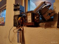
Anyhow so as to show my support if Any Ukrainians are Planning some Counter attack, sabotage or whatever,
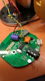
i have a Good oL Crank Detonator
We used to play around with as kid's.... 🙂
And godarn does it detonate, it almost
Detonated Me trough the Roof, when a while back i decided to test it with just putting my hands on the Terminals...... BaaaaaD Sweet 🙂
(did'nt thought much of it there and then, Or Rather i thought what the heck can't be that Many volts since when i was younger we (Let's just say it as it is) Came Accross some 225 kg Dynamite & Two Spools of Detonating cord, So then We always just used a car battery, or somtin along those voltages, the point is, It just has to heat the coil in Det Cap....
Anyhow i could not be MoRe Wrong.!! 🙂 🙂
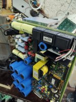
That Blody crank Beast.!! Delivered some litterally BoDy shock Jolting 1100 Volt on it's Terminals.... Woooow & aauch that hurt, i later then just had to inspect it and found two 8 micro/800 Volts Cap inside,?
what the heck.?? Are they planning on Cabling to and detonating something in another Solar System banking for so much R losses it probably could.... Anyhow Pics Of The Beast As it has become known, in these Circles.... 🙂
Anyhow so as to show my support if Any Ukrainians are Planning some Counter attack, sabotage or whatever,
i have a Good oL Crank Detonator
We used to play around with as kid's.... 🙂
And godarn does it detonate, it almost
Detonated Me trough the Roof, when a while back i decided to test it with just putting my hands on the Terminals...... BaaaaaD Sweet 🙂
(did'nt thought much of it there and then, Or Rather i thought what the heck can't be that Many volts since when i was younger we (Let's just say it as it is) Came Accross some 225 kg Dynamite & Two Spools of Detonating cord, So then We always just used a car battery, or somtin along those voltages, the point is, It just has to heat the coil in Det Cap....
Anyhow i could not be MoRe Wrong.!! 🙂 🙂
That Blody crank Beast.!! Delivered some litterally BoDy shock Jolting 1100 Volt on it's Terminals.... Woooow & aauch that hurt, i later then just had to inspect it and found two 8 micro/800 Volts Cap inside,?
what the heck.?? Are they planning on Cabling to and detonating something in another Solar System banking for so much R losses it probably could.... Anyhow Pics Of The Beast As it has become known, in these Circles.... 🙂
Attachments

If you like fireworks just connect supply caps with polarity inverted and replace mains fuse with rolled up aluminum paper.
Then stand back and flip power switch ON 🙂
Then stand back and flip power switch ON 🙂
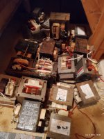
some 10-15 years back i envisioned to build / ProtoType A single ended Inductance Loaded Amp...
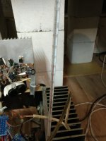
And Grabbed Each and every Microwave Oven i could Get My Hands on,
(Also for a while used one of those to power my home buildt, Dual Eimac 3-5ooZ Tube,, 7 - 28 Mhz 5 Bands 1200 watts Amp) Altough i dont think they are meant to run continously As they Got Extremely HoT...
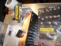
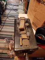
And it's quite obvious when one see WeLded laminating plates, So the eddy currents probably shot trought the roof.... Anyhow's then came the problem of choice... see pics
i have only a Few Of what i think is the best ones and also almost twice as large, And Most Importanly It Has Bolted Cores NOT Welded as should be... 🙂
i Think they belongs to some of the oldest micro wave ovens Back when it was legal with 3 Kw of micro wave Power.... 🙂 😎
And Grabbed Each and every Microwave Oven i could Get My Hands on,
(Also for a while used one of those to power my home buildt, Dual Eimac 3-5ooZ Tube,, 7 - 28 Mhz 5 Bands 1200 watts Amp) Altough i dont think they are meant to run continously As they Got Extremely HoT...
And it's quite obvious when one see WeLded laminating plates, So the eddy currents probably shot trought the roof.... Anyhow's then came the problem of choice... see pics
i have only a Few Of what i think is the best ones and also almost twice as large, And Most Importanly It Has Bolted Cores NOT Welded as should be... 🙂
i Think they belongs to some of the oldest micro wave ovens Back when it was legal with 3 Kw of micro wave Power.... 🙂 😎
Attachments

He he 🙂Aluminum foil isn't as good as using a nail 😛
one would'nt Get much insurence money if the house burned down then.. 🙂

In RF it is very much so because at RF very pure iron are almost insulating,, Or at least a **** poor Conductor, and especially when one Creeps above 2o-3o Mhz..... 🙂Aluminum foil isn't as good as using a nail 😛
i once could not understand why i had an extremely Poor Standing.Waves.Ratio.,, And could not seem to Get Brute Power uP into my antenna, and so later discovered that my main RF grounding bar had seem to been blown apart by lightning strike,, and the ONLY Thing / ReturnPath Was trough a steel Mount / fastening system.... 🙂Aluminum foil isn't as good as using a nail 😛
No wonder i could not Get The Power output uP To couple hundred watts, over The KW.............. 🙂 😎 🙂
oooh Yeah would you look at that 🙂 it seems to not only fit, but nice and snug too... 🙂 😎And copper pipe seems to be the same diameter as a cartridge fuse LMAO
View attachment 1043000
Is the bus crossing copper rod or whatever some kind of Saftey feature,, he he or if someone was to throw the power back,, Exposion feature hi hi 🙂And copper pipe seems to be the same diameter as a cartridge fuse LMAO
View attachment 1043000
oooooh Yeaaah 🙂
i just recently found out that MTV had both Channels for three decades,, 80, 90, 00's Oooh man this 90's channel just Roll Of The One Goooood Ol Memorable Song After the Other...... 🙂
Cheer's & clink 🙂 Good & Esteemed People
i just recently found out that MTV had both Channels for three decades,, 80, 90, 00's Oooh man this 90's channel just Roll Of The One Goooood Ol Memorable Song After the Other...... 🙂
Cheer's & clink 🙂 Good & Esteemed People
- Home
- Member Areas
- The Lounge
- Someone who would Know Or Rekognize Winding Ratio on these Transformers :-)