Dear Diyaudio friends,
I have this question I would like to share with you, any help would be appreciated.
I have a Yamaha CA-1010 I want to fully recap (the electrolitics) for reliability, and do "regular maintainance things": replace the heatsink glue and relays, new binding posts, lamps to LED conversion.
But besides that I would like to do some upgrades, to make the circuit from 1978 a little more up-to-date performance-wise. It seems to me there are a lot of cheap upgrades to increase the reliability and performance:
My suggestions:
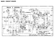
The schematic for the main pcb is attached.
My question is are these good modifications or do you suspect problems like high frequency oscillation or fire hazard? I have read a lot on Diyaudio which has helped to form these ideas, but I have no practical experience with it, so I'm affraid that I'm missing some things with my implementation. I am aware that the substitutes must fit the board (same lead spacing and enough room on the board).
Cheers.
I have this question I would like to share with you, any help would be appreciated.
I have a Yamaha CA-1010 I want to fully recap (the electrolitics) for reliability, and do "regular maintainance things": replace the heatsink glue and relays, new binding posts, lamps to LED conversion.
But besides that I would like to do some upgrades, to make the circuit from 1978 a little more up-to-date performance-wise. It seems to me there are a lot of cheap upgrades to increase the reliability and performance:
My suggestions:
- Replace all ceramics by WIMA polypropylene (all values lower than 1 uF). (Note: C314 and C315 will be a 40 VAC part but C317 and C318 a 400 VAC EPCOS MKP)
- Change the local decoupling caps of 1 uF / 80 V by 100 uF or 220 uF
- Replace trimpots by Bourns multiturn trimpots
- Change R330,R331,R337,R338 by noninductive resistors
- Change all fusible resistors with 2 W metal film resistors
- Change VD-1212 by two 1N4148 in series
- Move the 100 uF / 6.3 V DC-blocking cap off-board (before the IN connection) and replace it by 3.9 uF polypropylene (-3 dB cutoff goes to 1.5 Hz). Reason: it will not fit on-board
- Bandwidth-limitation, I simulated -3 dB cutoff at 222 kHz if C303 (220 pF) is replaced by 2200 pF part.
The schematic for the main pcb is attached.
My question is are these good modifications or do you suspect problems like high frequency oscillation or fire hazard? I have read a lot on Diyaudio which has helped to form these ideas, but I have no practical experience with it, so I'm affraid that I'm missing some things with my implementation. I am aware that the substitutes must fit the board (same lead spacing and enough room on the board).
Cheers.
Attachments
If you are good with desoldering and have the fine feeling then you can try this, but I do not recomend you to move the 100 uF / 6.3 V DC-blocking cap off-board (before the IN connection) and replace it by 3.9 uF polypropylene (-3 dB cutoff goes to 1.5 Hz). Reason: it will not fit on-board.If you replace C303 by 2200 pF part it will be bad for high frequency signals.But 100uF is a way to much for this, I think a 10uF will do it too.
hello.
i think too a 10uf/35v.......63v input elco is big enough.......
and 2200pf for c303(220p) is too big because if you have a preamp or a volume pot with high output impedance treble will be cut off. i would use 220pf as in the schematic shown.
make the upgrades step by step and test the amp after every tweak carefully (offset at the output,................listening tests).
greetings.
Do you have a plan for measuring any changes/improvments? For instance when increasing the value of the local bypass caps by a factor of X100, will you measure the effect? Pardon me, if I sound a bit skeptical, but a baseline quantative evaluation needs to be done before any "modifications" ---this is for your own good. I see this all of the time on the forum, folks asuming that mods that they herd about on the net must be an improvment, I mean the guy said it worked on his XYZ amp and so it must be good for my amp too. In any case, do it one step at a time, and make measurments! Frankly it sounds like you have been caught up in the "WIMA polypropylene" rage that is mostly mystical. Please say it isnt so!
Thank you. Why would it be bad? The 3.9 uF cap would be glued somewhere, with a wire attached going to R301 and bypassing the pcb track from IN to R301 (this track is about 10 cm long). Contrary to polypropylene, polyester would fit on-board, so that would be a safer option.If you are good with desoldering and have the fine feeling then you can try this, but I do not recomend you to move the 100 uF / 6.3 V DC-blocking cap off-board (before the IN connection) and replace it by 3.9 uF polypropylene (-3 dB cutoff goes to 1.5 Hz). Reason: it will not fit on-board.
I assume you are referring to the DC-blocking cap. Actually, the schematics differ from the real amplifier here, it has a 10 uF / 6.3 V cap as you and mjf suggested. Which indeed is well suited for the job (-3 dB at 0.7 Hz).But 100uF is a way to much for this, I think a 10uF will do it too.
I did not include a high output impedance source in my simulation, I will have to redo that. Thanks for noting!and 2200pf for c303(220p) is too big because if you have a preamp or a volume pot with high output impedance treble will be cut off.
I agree. Regarding ceramics vs polypropylene, maybe I'll do one channel first so I can make some comparisons. I already have a scope, maybe a test load would also be recommended.make the upgrades step by step and test the amp after every tweak carefully (offset at the output,................listening tests).
Firechief, this is the kind of reply I really appreciate. I have a scope and pc signal generator software and think I should build some power resistors for testing. I hope this is enough equipment for doing measurements. I will mostly look at square wave behavior.
I would like to be able to measure THD spectra with my computer but in this I didn't succeed.
For example the local bypass capacitor increase, I found a lot of amps use 100 to 220 uF here and a "critic" of this amp has been that it loses authority on large volume levels. And my (wild) guess is that back 1978 a 100 uF electrolytic would have to high an ESR for the application and film was to expensive, but now a 100 uF lytic with low enough ESR would exist.
Well, yes I have caught the "polypropylene is better than ceramic" bug unfortunately. I have built a parts order list and found WIMA has a nice form factor and decent price.Frankly it sounds like you have been caught up in the "WIMA polypropylene" rage that is mostly mystical. Please say it isnt so!
Leon and mjf, as you both pointed out 2200pF is to high, I redid simulation with output impedance and wire capacitance. Even in my current setup (output impedance 560 Ohms, estimated wire capacitance 220 pF) it would have a lowish high-frequency cutoff of -3 dB @ 80kHz. I have read -3 dB @ 200-300 kHz advocated. It will stay 220 pF, this simulated good response with a source with up to about 2 kOhms output impedance.
I agree with the one change at a time philosophy. I replaced the paper caps in my PAS2 with polyester (some) and polyprophylene (others), did two at a time, and really couldn't hear much difference- except for the paper one where the case was burned through at installation, was probably off value due to water and was causing my channel imbalance. **** minister that built it, hid the burned part of the wax case under the cap. Won't stop water in the air, like trying to hide sin from God, he should have known better.
I used a 10uf 50V Aerovox ceramic cap on my input of the ST120 instead of a 10uf tantalum cap. Sounds pretty good, and got rid of the low frying pan noise it was making. a serious expert on this board told me how stupid this was after I did it, but haven't gone back and redone it, the amp sounds pretty good. Ceramics are non-linear and he has data that proves how bad they are as output caps or speaker crossover filter caps, but the input cap is subject to very low voltage swings, and I used 50 V rated ones which are the highest voltage I could buy in 10 uf. I think that is why I am not experiencing any audible distortion-actually improved the sound due to the frying pan crackle. Putting the input cap on the PCB is probably important, due to the high gain of this point and the external connection to noise from the outside. The risk of having the cap remote is possible oscillation started by noise coming in. But, have fun, do one change at a time, and back up if you can't get away with what you did.
I used a 10uf 50V Aerovox ceramic cap on my input of the ST120 instead of a 10uf tantalum cap. Sounds pretty good, and got rid of the low frying pan noise it was making. a serious expert on this board told me how stupid this was after I did it, but haven't gone back and redone it, the amp sounds pretty good. Ceramics are non-linear and he has data that proves how bad they are as output caps or speaker crossover filter caps, but the input cap is subject to very low voltage swings, and I used 50 V rated ones which are the highest voltage I could buy in 10 uf. I think that is why I am not experiencing any audible distortion-actually improved the sound due to the frying pan crackle. Putting the input cap on the PCB is probably important, due to the high gain of this point and the external connection to noise from the outside. The risk of having the cap remote is possible oscillation started by noise coming in. But, have fun, do one change at a time, and back up if you can't get away with what you did.
Last edited:
Yes, I'll probably buy both polypropylene caps and polyesters so I can try out off-board polypro first and if produces audible hum then the polyesters on-board.
I'll also try a X2 noise suppresion cap across the transformers primary and see with scope if it produces a cleaner rectified voltage. I've seen mixed opinions about using noise suppresion caps in the PSU.
I'll also try a X2 noise suppresion cap across the transformers primary and see with scope if it produces a cleaner rectified voltage. I've seen mixed opinions about using noise suppresion caps in the PSU.
- Status
- Not open for further replies.
- Home
- Amplifiers
- Solid State
- Some upgrades to vintage amplifier