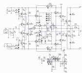
I modified this schematic from original voltage feedback topology which I had designed 75WRMS/CH.
I use some of idea from input stage of Accuphase E407 and use driver/power from my original schematic.
In the future I'll control it into class-a such as Krell KSA50 (hope).
Please suggest me if I had wrong design
Regard
AHT
I use some of idea from input stage of Accuphase E407 and use driver/power from my original schematic.
In the future I'll control it into class-a such as Krell KSA50 (hope).
Please suggest me if I had wrong design

Regard
AHT
Attachments
Hi,
You use some simulation program to do that sch and simulate probably - which one if this is not a secret - and .... where to find simulation models for other types of devices?
I this sim good (if You use it offcourse)?
I am not an expert on solid state (more in tubes acctually - so I wouldn't like to expertise arround Your circuit - but it looks nice and interesting from what I could see) but would like to try few things - first sim than build so a good sim would be nice.... maybe You could help...
bes regards
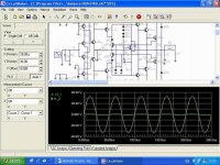
Ok...following picture
I use 2.305mA for first stage Q3,Q5,Q1,Q4 and 2.404mA for current feedback stage Q2,Q6 and use 95mA for idle current on output Q16,Q17.
My schematic can be operate in bandwidth around 1-1MHz from CFA theory and it use over current protection ,too
For DIYER PCB coming soon 🙂
ECG188/189 = MJE15030/31
ECG87/88 = MJ15024/25
Attachments
Cool !!!....simulation nearly succeed
From my experience about a voltage feedback amplifier I think a current feedback amplifier quite good flat sound (from simulating) anf more stability than VFA but I don't know why there're some (a few) brand name use CFA ? such as Accuphase, Arcam, Denon, Marantz, Jeff Rowland, as well as it's a good designing and a new topology.
Or I don't know about schematic of hi-end brand as use CFA 😕
Attachments
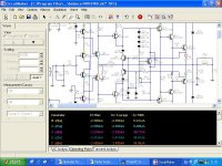
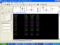
picture of truely current at each stage
Following point :
A=Q3,B=Q5,C=Q1,D=Q4,E=Q2,F=Q6,G=Q7,H=Q8,I=Q12,J=Q13,K=Q14/15,L=Q16,M=Q17
After I simulated I just understand a theory of CFA it's as same as typical VFA but there's a few concept that adventage more than VFA such as
1.Slew rate
2.THD
3.Stability
4.Frq response
5.Sound (I think so)
Now I'm completely start to work with CFA 100% if anybody have other idea please suggest me, too
Regard
AHT
Attachments
Re: Cool !!!....simulation nearly succeed
AD844,OPA660....etc is the same topology as the sch you post.😉
X.G.
Add a few brand:BB,AD.....😀aht said:From my experience about a voltage feedback amplifier I think a current feedback amplifier quite good flat sound (from simulating) anf more stability than VFA but I don't know why there're some (a few) brand name use CFA ? such as Accuphase, Arcam, Denon, Marantz, Jeff Rowland, as well as it's a good designing and a new topology.
AD844,OPA660....etc is the same topology as the sch you post.😉
X.G.
One quick comment; the 660 Ohm working against a Vbe and 82.5 Ohms in the first stage is a little dicey with respect to temperature stability. You might not need the little gain boost you get, and might just go with a current mirror arangement instead.
- Status
- Not open for further replies.
- Home
- Amplifiers
- Solid State
- Some topology of current feedback amplifier


