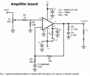
hello everyone, I was trying to understand the lm3386 schematics of briangt. I only see v-, v+ on the schematic but according to PCB there should be also +pgnd, -pgnd and chg. Where are they? Are they all the same = ground?
Also I don't see the input, output pads on the pcb?
Finally what's the aim of S1? is that the power switch? shouldn't it be on the psu board between mains and transformer? (obviously not but I need to understand why 🙂)
EDIT: I noticed that briangt schematics has R2, RZ and CZ extra comparing to the national semi. schematics: http://www.national.com/mpf/LM/LM3886.html
What are these for?
sorry if I'm being a complete noob, thanks in advance for the replies.
Attachments
ok, I figured out almost everything by looking the build pictures.
I still don't know what R2, RZ and CZ do though. Anyone?
I still don't know what R2, RZ and CZ do though. Anyone?
Ted205 said:Rz and Cz are a zobal network (google it 😉)
R2 sets a consistant input impedance
See also this topic
http://www.diyaudio.com/forums/showthread.php?threadid=129564
Peter Daniel inform First one ChipAmp builder about Rz Cz and Rm
Trooper46 said:well after doing a fair amount of reading i purchased a lm4780 kit from audiosector. after sitting around with the kit for some time now i finaly started it tonight. i'm not really all that good with a soldering iron but i did try my best.
has any one built this kit?
i am afraid i do not know what cz, rz, and rm are. i could not find them in any of my packets of parts. maybe they are optional? any insight would be great.
also i still am undecided if i am going to run the chips bridged, parallel, or just make 2 stereo amps.
see the pic for whats done so far and the heatsink i plan on using.
thanks for the clarification.
lineup: I see that one of the reasons you recommend using zobel is because NS says so but in the official datasheet schematic there is no Cz Rz?
lineup: I see that one of the reasons you recommend using zobel is because NS says so but in the official datasheet schematic there is no Cz Rz?
Offline
Registered: Dec 2005
Location: in your thoughts
Post #12
I would recommend using them.
Why?
Answer:
1. Because some loudspeakers will REALLY need them.
Some speakers would fool you that Zobel is not needed.
Next time your amplifier will make one Burn Out in Smoke, of your new set of LoudSpeakers
Would you really like this?
2. Because they are recommended by those making these Amplifier Chips!
3. Because the designers should know better than anyone, what is safe use of LM3875 & LM3886.
4. Because some AudioPhiles are not very smart .. at least compared by
National Semiconductor worldwide big, big company Technical Engineers staff
.. and neither am I, Lineup
5. But I am actually smart enough to give people some good advice
.. to prevent unnecessary DISSASTER
Lineup
Your post #12 sums it up
Some have the idea that chip amps are only one step from being something made from the Gods. You need to see them for what they really are. Chip amps are very primitive and well suited for those incapable of building anything much more complex. Its a simple little amplifier that can be put together in 1/2 hour or less that provides a so so performance. Some are making a few bucks here by selling their custom kits which seem to have forgotten some of the principals of amplifier design and safety. The Zobel is a necessity in any amplifier and certainly a safeguard for those new speakers that one prizes so highly. The idea that one could hear a difference between having a Zobel in the circuit is well for me totally 😀 laughable to say the least.
I always am willing to trust the experts. Peavey for example still manufactures a small commercial amplifier that employs a chip amp. The UMA 12 and 10 use the smaller chip amp. I might add that they also use a Zobel network in their designs. I will also add that these amplifiers have a history of blowing up if loaded heavier than about 6 watts on a 70volt line.
Sometimes you will find engineering schematics that are concept designs. Sometimes these actually work and sometimes they don't. You the builder have to rely on your experience and common sense to come up with something workable that will live.
I also built one of these beauties just for grins. I modded it, tested it, and listened to it. My finale decision is that a person could find a more accurate, musical amplifier if one purchased a good used amplifier of quality in the first place. After all there is only so much one can make out of a sows ear.
Speaking about sound engineering…
As was claimed, R2 does not set constant input impedance! When you view it in reference to ground it is in parallel with series connection of R1 and wiper-ground resistance of the RIN potentiometer. That is far from constant!
Furthermore, the said constant impedance we are interested in the most is that seen by the chip’s inputs and regarding DC current. Preferably both inputs of the chip (inverting and non-inverting) should to see the same DC resistance to ground. If Ci is used the DC is referenced to ground via series connection of Rf and Rl (speaker load). We can pretty much ignore the last. Since the non-inverting input should see the same DC resistance in reference to ground one should fit a capacitor in series with R1. Then Rf should equal R2. Due to cap this condition will not change when volume pot is adjusted.
If Ci is not used then R2 should equal parallel resistance of R3 and Rf.
If this issue is not taken care of the circuit will generate DC offset. As far as I see, it is likely the best solution to DC couple the input after the volume pot. This both removes all issues of DC offset originating from the source and provides the necessary constant impedance for DC seen by the chip inputs. Audiophiles of course disagree since we all know how bad capacitors are for the audio quality, don’t we?
Input impedance for AC signals will still naturally drift when pot is adjusted but in any case it remains higher than 10K, which is ok for most signal sources as they often have source impedance that is less than 1K. This still provides sufficient impedance bridging.
I would also fit a RF suppressor cap in parallel with R2 and possibly a few picofarad cap in parallel with Rf to limit the high frequency gain. Maybe put a series resistor to this cap. I believe it is also shown in datasheet’s schematics. In any case I would at least leave slots for them in the PC board, just in case. I think only quite a few people from those building these gainclone things actually realize how conceptual the datasheet schematics really are.

- Status
- Not open for further replies.
- Home
- Amplifiers
- Chip Amps
- some questions about briangt schematics