Your outputs are drawing grid current on positive peaks. Is this intended? Is the output bias correct?
No I do not want it to draw grid current. I do not know if the bias is correct or not. The only adjustment is balance, and I balanced the cathode currents.
I measured the voltages right now. Does it look like bias is correct?
Location * No Signal * Full Power * Schematic's stated value
Anode ****432 ********* 422 *********** 425
Screen *** 436 ********* 426 *********** 428
Grid ******* 2.9 *** ac confused dmm *** 2.8?
Cathode ***39 *********** 43 ************ 36 or 38??
When I scoped it just right now, it the top half wasn't being cut off so sharply but the bottom was being strangely elongated. I don't remember it doing that before. The top trace is the drive to the grid and the bottom trace is the output at my dummy load. Output was still 40v peak to peak into 8 ohms which I think is 25w.
An externally hosted image should be here but it was not working when we last tested it.
The elongation on the bottom of the grid drive is caused by the feedback loop trying to correct the clipping, probablt caused by the 'other' output grid also having grid current on peaks. You don't see it on the positive peak because the grid current lops it off.
As your bias looks to be as intended, then it could be that the anode load is too small. Can you try using a larger dummy load, say 12ohms instead of 8? 16ohms might work, although maybe getting too large. The idea is to see what output power you can get into a higher load, at the verge of clipping. If the maximum power increases with load resistance, then your transformer ratio is wrong. Are you using a 16ohm output tap by mistake?
As your bias looks to be as intended, then it could be that the anode load is too small. Can you try using a larger dummy load, say 12ohms instead of 8? 16ohms might work, although maybe getting too large. The idea is to see what output power you can get into a higher load, at the verge of clipping. If the maximum power increases with load resistance, then your transformer ratio is wrong. Are you using a 16ohm output tap by mistake?
That explains the elongation - I did not have the feedback connected before when testing.
Here are the test results for different connections and dummy loads.
Dummy R * wire - colors * V p-p * Watts
16 ********** white-orange * 35 ** 9.8
16 ********** white-yellow * 45 ** 16.1
16 ********** white-green * 55 ** 24.1
8 ********** white-orange * 33 ** 17.4
8 ********** white-yellow * 39 ** 24.3
8 ********** white-green * 30 ** 14.3
4 ********** white-orange * 27 ** 23.2
4 ********** white-yellow * 22 ** 15.43
4 ********** white-green * 18 ** 10.3
12 ********** white-orange * 35 ** 13.0
12 ********** white-yellow * 44 ** 20.5
12 ********** white-green * 44 ** 20.5
Edcor says white=common, orange=4ohms, yellow=8ohms, green=16ohms.
My dummy load is made of wire wound resistors, but I used a number of 1 watt carbon comp resistors to add the additional 4 ohms for the 12 ohm test.
OK, another theory bites the dust. You are clearly getting maximum output in each case on the appropriate secondary tap.
Bear in mind that the difference between 40W and 25W is only a 20% drop in voltage. Is your HT drooping under load? Could the original amplifier do 40W continuous sine wave, or was it 40W on music peaks - i.e. no HT droop, not output bias shift?
The article talks about 80-100V grid drive. I'm not sure what this means, given a 38V bias. Even 80V pk-pk would push a bit of grid current.
Everything is right; and an article specified 30W only output transformer. 80k p-p means driver stage is fine to deliver needed voltage so it will be limited by grid currents, not by the driver stage itself.
http://stiftsbogtrykkeriet.dk/~mcs/Williamson/ppwil001.gif
In the above link, there is a graph showing the performance of the amplifier up to 45 watts.
I am a bit confused...
The voltage sags 10 volts with high vacuum rectifiers and 5 volts with argon or mercury rectifiers. Power output with the latter types is is couple watts more, probably due to higher plate volts and current.
What would happen if I increase the cathode resistor to increase bias, and increased the plate voltage by a corresponding amount? Or would that have bad side effects?
I figured it out. It is, in fact, only supposed to put out 30 watts. The power on that intermodulation distortion graph was "equivalent sine wave power", which is equal to 25/17 times the measured rms power of the sum of two different sine waves which are fed to the amp during the test. See here: greygum.net/files/radiotronics/intermodulation-A515.pdf
I inputted two sine waves at the same time as shown in that pdf and measured the total output as 27 watts (w/ MV rectifiers) which equals 40 watts "equivalent sine wave power". Close enough! 😱
So the last thing to do before this thing is officially finished is to complete the gNFB system. I put a 120pf variable capacitor across the feedback resistor, but the only thing that I find it does as I increase capacitance is increase high frequency feedback with a result of decreasing high frequency gain. I don't want that, do I? What is it supposed to do? 😕
I've lost track which circuit diagram you have built to. We need to see your final version for the global nfb. Without it, a wild goose chase. As square wave generator will greatlym assist.
Got Some 1kHz squarewaves to show us ?
richy
Got Some 1kHz squarewaves to show us ?
richy
Here is the original circuit: https://mywebspace.wisc.edu/jdelventhal/Tube_Amp/ppwil002_v2.gif
Here is my version, changes in red: https://mywebspace.wisc.edu/jdelventhal/Tube_Amp/SchemeC.png
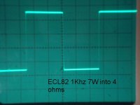
Here is 1khz square waves (or at least as square as my laptop can make them). The trimmer capacitor(C3) is set to minimum and the feedback resistor is 18K as specified by the schematic. Top is input, bottom is output: https://mywebspace.wisc.edu/jdelventhal/Tube_Amp/comp.JPG
Here is the difference between the two waves: https://mywebspace.wisc.edu/jdelventhal/Tube_Amp/dif.JPG
Increasing the trimmer capacitor slightly increases those little bumps in the last picture. Snipping off C11 slightly reduced them.
Here is my version, changes in red: https://mywebspace.wisc.edu/jdelventhal/Tube_Amp/SchemeC.png
Here is 1khz square waves (or at least as square as my laptop can make them). The trimmer capacitor(C3) is set to minimum and the feedback resistor is 18K as specified by the schematic. Top is input, bottom is output: https://mywebspace.wisc.edu/jdelventhal/Tube_Amp/comp.JPG
Here is the difference between the two waves: https://mywebspace.wisc.edu/jdelventhal/Tube_Amp/dif.JPG
Increasing the trimmer capacitor slightly increases those little bumps in the last picture. Snipping off C11 slightly reduced them.
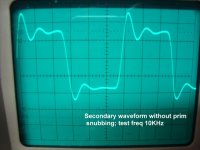
YOUR lower squarewave (output secondary) looks too good to be true. I was expecting over and undershoot like in the pic below. A typical example of a output waveform when things don't quite go to plan.. Sure you haven't got scope settings mixed up ?
I presume the "difference pip" between the two waves you are subtracting waveforms. I would ignore this, as one is trying to detect slight phase differences. I have mixed views regarding C11; much depends on output tranny quality.
I notice the squarewave rise and fall is heavily slewed, i.e HF response curtailed to 20Khz or lower. In the other pic is when all ailments have been sorted out, the typical squarewave response with the amplifier -3dB @55Khz. It all depends on the layout and o/p tranny.
You should be quite lucky (proud) what youv'e got !! That is for real. The next bit is how does it sound ?
Attachments
Last edited:
Scope settings are fine. I suspect that my laptop is not producing a square enough wave to properly challenge the amp.YOUR lower squarewave (output secondary) looks too good to be true. I was expecting over and undershoot like in the pic below. A typical example of a output waveform when things don't quite go to plan.. Sure you haven't got scope settings mixed up ?
I think it sounds best with no global feedback capacitor, and it does not seem to really effect the square wave response that I can see, so I think I will just leave it out. If at some point I buy a real square wave generator, I may recheck it.The next bit is how does it sound ?
I am declaring this amplifier successfully finished. Thanks for all the great help from many forum members over these last few months.🙂
- Status
- Not open for further replies.
- Home
- Amplifiers
- Tubes / Valves
- Some questions about an amplifier design