Hi! 🙂
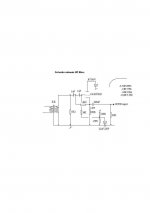
I thought it would be fun to build a tube amp over the summer. This design looked pretty good but I have a few questions. http://stiftsbogtrykkeriet.dk/~mcs/Williamson/ppwil002_v2.gif
My first question is, can I substitute 807's for the 1614's? From what I could find , they both seem to be glorified 6l6's, but with the 807's having somewhat higher voltage ratings.
If you have a nice supply of 807's, use 'em. The Williamson topology shown requires the use of PREMIUM quality O/P trafos and that's EXPENSIVE.
Are you building monoblocks?
Are you building monoblocks?
I was hoping to make one big stereo amp to save on some power supply components.
What do I need to look for in an output transformer, that say, a Hammond or an
Edcor would not have?
What do I need to look for in an output transformer, that say, a Hammond or an
Edcor would not have?
No way is a Hammond O/P trafo up to the task of Williamson style circuitry. Phase shifts will eat you alive. You might get away with Edcor. IIRC, a member did a Williamson with Edcor recently. Still, I much prefer Mullard style circuitry with budget "iron", as stability trouble is much less likely.
Edcor's model CXPP60-8-6.6K looks about right for 6L6 family tubes, like the 807s you have in mind.
If a stereoblock is to be constructed, SS rectify the B+ and avoid worrying if vacuum rectifiers can handle the B+ draw. Also, sourcing good 5AR4/GZ34s has become problematic. If your heart is set on using vacuum rectification, employ a pair of 6AU4 damper diodes.
I built the amp in the article you linked to, back in 1970 when I was 13.
I used 1625's for the output tubes. The 1625 is a 12 volt heater version of the 807. It was and still is super cheap.
I also used 12AU7's in place of the 6SN7's.
I used a BUD 17'*13"*3" chassis and built a stereo version. It was the first brand new chassis I ever had. It took a month of skipping lunch in the school cafeteria to save up for it.
It worked great.
I still have it.
If you have any questions let me know.
Also consider this design: http://greygum.net/files/radiotronics/PP807-A515.pdf
From the figures at the end of the text it appears to have constantly low distortion from approx. 2 to 10 W.
It is a Williamson modified by F. Langford-Smith, the gentleman behind the Radiotron Designer's Handbook.
From the figures at the end of the text it appears to have constantly low distortion from approx. 2 to 10 W.
It is a Williamson modified by F. Langford-Smith, the gentleman behind the Radiotron Designer's Handbook.
Thanks for the info.
Eli, would it be at all problematic using that 60w opt when a 30w one is specified? Would I be better off using their 45w version?
My preference for rectification would be a pair of 866a's, (because I have a lot of them), but I see that those damper diodes could run off the same filament transformer as the rest of the tubes which is a significant advantage.
DrRick, it is good to hear that you actually built it, so I assume that it must a reasonably good design.
Gordy, I saw that design too but I was hoping for just a bit more power.
-------------------------------------------------------
I need a little advice on the power supply:
To scale it up to supply power to both channels, I assume I just need to double transformer mA, halve the inductance and resistance of the chokes, and double the capacitance. I had to adjust some values to what parts are available. I am considering using the Hammond 715 which is 115v to 510-0-510v @300mA. Adjusting for 120v input, I get 510*120/115 = 532v. Using Hammond s cheat sheet I get output mA = secondary mA*1.54 for a choke input filter. This gives 462 mA which is more than enough.
So I download PSUD and simmed the "adjusted" PSU at 400mA and 280mA drain and got this:
This seems pretty good, except the voltage might be a little low depending on the current draw for which the measurements given in the schematic are given. Additionally, three pulses exceed the 2A max current capacity of the 866's on startup while charging that large capacitor, so I would probably need something to limit the current inrush, if I decide to actually use the 866's. I also tried simming it with the damper diodes but this dropped the b+ voltage by 25v, so I would probably need to buy a custom power transformer if I used them.
Because the peak to peak ripple voltage was only was only 16mV, and I read hear that pp amps are o.k. with up to about 1v of ripple, I decided to try eliminating one of the chokes. Here was the results:
Ripple voltage was now a still reasonable 500mV but $60 and a lot of space would be saved. Additionally, a resistor was added in series with the choke to drop b+ a bit which would seem to allow more tweakability. In fact, without that resistor, the damper diodes produced sufficient voltage output.
I'm new at this; my tube experience only involves repair. Am I on the right track? Is there a problem with eliminating that choke that I am overlooking?
Eli, would it be at all problematic using that 60w opt when a 30w one is specified? Would I be better off using their 45w version?
My preference for rectification would be a pair of 866a's, (because I have a lot of them), but I see that those damper diodes could run off the same filament transformer as the rest of the tubes which is a significant advantage.
DrRick, it is good to hear that you actually built it, so I assume that it must a reasonably good design.
Gordy, I saw that design too but I was hoping for just a bit more power.
-------------------------------------------------------
I need a little advice on the power supply:
To scale it up to supply power to both channels, I assume I just need to double transformer mA, halve the inductance and resistance of the chokes, and double the capacitance. I had to adjust some values to what parts are available. I am considering using the Hammond 715 which is 115v to 510-0-510v @300mA. Adjusting for 120v input, I get 510*120/115 = 532v. Using Hammond s cheat sheet I get output mA = secondary mA*1.54 for a choke input filter. This gives 462 mA which is more than enough.
So I download PSUD and simmed the "adjusted" PSU at 400mA and 280mA drain and got this:
An externally hosted image should be here but it was not working when we last tested it.
This seems pretty good, except the voltage might be a little low depending on the current draw for which the measurements given in the schematic are given. Additionally, three pulses exceed the 2A max current capacity of the 866's on startup while charging that large capacitor, so I would probably need something to limit the current inrush, if I decide to actually use the 866's. I also tried simming it with the damper diodes but this dropped the b+ voltage by 25v, so I would probably need to buy a custom power transformer if I used them.
Because the peak to peak ripple voltage was only was only 16mV, and I read hear that pp amps are o.k. with up to about 1v of ripple, I decided to try eliminating one of the chokes. Here was the results:
An externally hosted image should be here but it was not working when we last tested it.
Ripple voltage was now a still reasonable 500mV but $60 and a lot of space would be saved. Additionally, a resistor was added in series with the choke to drop b+ a bit which would seem to allow more tweakability. In fact, without that resistor, the damper diodes produced sufficient voltage output.
I'm new at this; my tube experience only involves repair. Am I on the right track? Is there a problem with eliminating that choke that I am overlooking?
In designs with GNFB, like Williamson and Mullard, magnetic headroom in the O/P trafo is essential. Otherwise, the deep bass error correction signal saturates the core. 🙁 Even with the headroom, an additional precaution is in order. Add a high pass cap. at the I/P, which in combination with the 1st grid to ground resistor yields a F3 in the 15 to 17 Hz. range.
Yes, it's possible for damper diodes and signal tubes to share a filament winding, but it's not a good idea. If you are comfortable with the hazards Hg vapor rectifiers present, you can use the 866As in your possession. Just make sure you have a well sealed container of powdered sulfur on hand. Should an envelope break, sprinkle Sulfur on the mess to sequester the liberated Hg. Don't forget to allow PLENTY of time for the rectifiers to get hot, before activating the HT winding. Frankly, I'd use damper diodes and a separate filament trafo for them. B+ rise is automatically very slow and there are no toxic waste issues.
Yes, it's possible for damper diodes and signal tubes to share a filament winding, but it's not a good idea. If you are comfortable with the hazards Hg vapor rectifiers present, you can use the 866As in your possession. Just make sure you have a well sealed container of powdered sulfur on hand. Should an envelope break, sprinkle Sulfur on the mess to sequester the liberated Hg. Don't forget to allow PLENTY of time for the rectifiers to get hot, before activating the HT winding. Frankly, I'd use damper diodes and a separate filament trafo for them. B+ rise is automatically very slow and there are no toxic waste issues.
In designs with GNFB, like Williamson and Mullard, magnetic headroom in the O/P trafo is essential. Otherwise, the deep bass error correction signal saturates the core. 🙁 Even with the headroom, an additional precaution is in order. Add a high pass cap. at the I/P, which in combination with the 1st grid to ground resistor yields a F3 in the 15 to 17 Hz. range.
6dB/oct; I find that isn't enough. I came across this problem using a octave shifter keyboard, where some shifting warbling subharmonics below transformer cutoff creates subharmonic blocking. This can occur with some synthesisers.
There are various Sallen-Key types about, but I use this low noise tube version, 18dB /oct; -3dB 15Hz. It can be improved but in it's current form has made the world of difference.
Tube amps with a good LF response can be particulary prone to subharmonic signals upsetting the GNFB loop. This implies with Plitrons the situation is far worse !
richy
Attachments
OK I built this thing but when I first turned it on, it made an awful sound and burned out my speakers.🙁 Since it sounded like something was oscillating, I disconnected the feedback wire from the output transformer. Now the amplifier works OK, at least as far as I can tell from some tiny speakers I salvaged from an old radio.
How do I fix it?😕
How do I fix it?😕
It sounds like the feedback was POSITIVE instead of negative. You need to change the phase somewhere in the amp. Probably exchange the two wires coming off the phase inverter so that they go to the opposite following grids would be the easiest. Before you power up an amp you need to use a dummy load and check all voltages first. Then use a signal generator and oscilloscope to check the signal before hooking up your speakers. If you are going to build your own electronics you need the proper tools. Consider them part of the cost of the amp.
Always try a new DIY amp first on a dummy load (a big resistor) not real speakers. The feedback phase may have been wrong, or it may be due to phase shift at LF or HF extremes.
Sorting out loop stability can be great fun, or very very frustrating. It depends partly on what test gear you have and how much you know about loop stability. In most designs you can reduce feedback by increasing the feedback resistor, thus improving stability. A lot of these early designs used too much feedback (in my opinion) in their pursuit of low THD figures, and ended up with marginal LF stability. Hence the need for excellent OPTs.
Sorting out loop stability can be great fun, or very very frustrating. It depends partly on what test gear you have and how much you know about loop stability. In most designs you can reduce feedback by increasing the feedback resistor, thus improving stability. A lot of these early designs used too much feedback (in my opinion) in their pursuit of low THD figures, and ended up with marginal LF stability. Hence the need for excellent OPTs.
I flipped the phase inverter wires around and it works fine. It did drop the output volume in half though. Is this normal? Also can I install a potentiometer to control the amount of feedback so I can tweak it to what sounds best?
GNFB will reduce gain. Sounds like you have it connected right this time. Do you have any test equipment?
Also can I install a potentiometer to control the amount of feedback so I can tweak it to what sounds best?
Yes, however keep in mind that you may be affecting the stability margin mentioned above and also keep in mind that the optimal parallel cap value will be different for various feedback R values. The proper C value can be empirically determined by inputting a square wave and looking at the output square wave on a scope. Adjust C to get the best looking square wave output.
The extent of my test equipment is a Harbor Freight DMM and VTVM which I bought because I keep frying those DMM's, but the VTVM doesn't work.
I wasn't sure whether the voltages should be tested with an input signal or not. I tested them without. Both channels were quite similar. Here are my results for the right channel:
https://mywebspace.wisc.edu/jdelventhal/volts.png
It seems B+ is high. The two channels only share fuse, plate transformer and thermistor, delay relay, and a pair of 3B28 rectifiers. The plate transformer is an Edcor XPWR-003, 550v-0-550v@ 400ma. The plate transformer is putting out 16v too much, probably because mains voltage is a little high today. A thermistor and the delay relay are in series with its primary. Each channel has its own filament transformer, choke, and hum pot . Instead of two chokes w/ 80ohms each DCR, I went with one choke per channel with 150ohms DCR. I figured the 3 volts or so extra that 10 ohms overall difference would drop would be made up by the slightly higher voltage drop of the 3B28s compared to the GZ34.
These two things don't add up to the 50 extra volts so I am a bit puzzled.
The other reading I found worrisome was the really low voltage on the plate of V2b. It was the same on both channels. I have no explanation, as the grids to ground, cathodes to ground, and plates to R19 resistances were equal respectively for both halves of the tube.
I could not measure the voltage on the grids of the output tubes because it made the cathode current meters swing wildly when I attempted to do so.
Besides messing with the power supply the only other changes I made were as follows:
CH1 10H instead of 7H. (couldn't find 7H w/ correct DCR)
R12 250ohms instead of 220. (couldn't find)
807's instead of 1614's (didn't have 1614's)
6F8G's instead of 6SN7's (much cheaper and harmonize better appearance wise w/ 807's).
Any thoughts on the B+ voltage or low plate voltage on V2b?
The amp sounds great by the way. Played it all day with my new speakers and it certainly seemed to work fine.
I would think that a first modern power outlets have more than 117 Volt, and I would check if output tubes are properly biased and draw current as supposed, so voltage drop on power supply is as designed.
My guess about voltages on anodes of power splitter tube can be caused by oscillations that can start or stop when you measure.
Edit: since the amp plays great, I would leave my guesses about higher voltage in power outlet, and oscillations that start when you touch anode by probe.
My guess about voltages on anodes of power splitter tube can be caused by oscillations that can start or stop when you measure.
Edit: since the amp plays great, I would leave my guesses about higher voltage in power outlet, and oscillations that start when you touch anode by probe.
Last edited:
I built the Williamson amp (mono blocks) over 10 years ago with Hammond 1650P output transformers. I used 807's and 6SN7's for the tubes. For the power supply, I used a SS rectifier for the plate and regulated DC for the filaments.No way is a Hammond O/P trafo up to the task of Williamson style circuitry. Phase shifts will eat you alive. You might get away with Edcor. IIRC, a member did a Williamson with Edcor recently. Still, I much prefer Mullard style circuitry with budget "iron", as stability trouble is much less likely.
I subsequently modified the first stage and phase inverter operating points slightly to bring them more into Class A compared to the original Williamson circuit.
They sound and measure great with the "crummy" Hammond transformers.
I finally got a scope (Tek R454) and determined that the weird voltage readings were in fact from high frequency oscillations from the DMM probe. I neatened up the wiring a lot and mounted all components except grid stoppers on turret boards and it no longer seems to oscillate so easily.
I also determined with the new scope that the wire colors on the OPT's primary were backwards, thus the speaker ruining oscillations, but I read that this is quite common.
I fixed the high B+ problem by replacing the 3B28's and 866A's that I was using with 836 high vacuum rectifiers. B+ is now 435 volts at full power like shown in the schematic. However voltage sag at full power has doubled and I miss the blue glow.
My question is, though, the amplifier starts clipping at only 25 watts. The cathode current per tube is 54mA at no signal and about 62mA at full power. The crest of the positive side of the sine waves from the drivers to the grids of the output tubes are being clipped off when the output tubes are start to clip. I think that is caused by the output tubes though, because when I disconnected the wire to there grids, the drivers were able to put out several times the voltage required to make the output tubes clip. Shouldn't this thing put out more watts? The magazine article showed it putting out more than 40 watts.
An externally hosted image should be here but it was not working when we last tested it.
- Status
- Not open for further replies.
- Home
- Amplifiers
- Tubes / Valves
- Some questions about an amplifier design