AFAIR we once discussed about your unity-gain point being a little high for your given switching frequency. The unity-gain point shall not be higher than 0.5 times the switching frequency. If you want to be on the safe side you make it 0.3 to 0.4. Otherwise you run into stability problems.
Regards
Charles
Regards
Charles
Yes, we discussed about that before...
Can that cause (0dB point being higher than fs/2) produce the effect I observe? (start of oscillations at power levels above 80% of clipping more or less, which severity depends on the load)?
Can this topology be unconditionally estable or will it always depend on the kind of load used?
I think I will increase the 33pF cap to around 56pF. My simulations look better, let's see what happens in the real world ;-)
Because the load is influencing the response of the output filter which is by itself a part of the loop you can indeed have such effects.
But the load can also be detrimental to the stability of the loop independant of Shannon/Nyqvist.
Regards
Charles
But the load can also be detrimental to the stability of the loop independant of Shannon/Nyqvist.
Regards
Charles
Thanks, Charles.
I will test some changes and come here with the final schematics and results, just in case anyone is interested on it...
Best regards
Pierre
I will test some changes and come here with the final schematics and results, just in case anyone is interested on it...
Best regards
Pierre
I have increased the sw. freq. from 260K to 360KHz.
On a resistive 3.4ohm load, all is fine about the ringing, better than before.
I expected that increasing the cap in parallel with the feedback resistor from 33pF to 56pF would improve things further, but in fact the contrary is true. I have put 15pF and the waveform is cleaner (and BW is somewhat bigger, as well 🙂 ).
However, I have tested with my bookshelf speaker, and with music with heavy bass notes at around 60% of max. amplitude, there is a clear superimposed oscillation, even worse than before, when the speaker is clearly distorting.
Can the thing be related to the behavior of the speaker when it is heavily overloaded?
What test can I do to reach peace of mind about estability of the amplifier without depending on a speaker? (I mean, excitation with a generator, let it be sine or square wave, on a given load formed by a combination of R, L and C's?) Is there a somewhat estandard test about this?
Best regards,
Pierre
Can the thing be related to the behavior of the speaker when it is heavily overloaded?
Maybe - but I tend to think that it is the combination of speaker impedance and modulation depth.
I think the worst load would be a purely capacitive one. Try with a cap that is at least the value of the output filter's cap then I think you will be on the safe side.
Regards
Charles
My amp has two cascaded output filters. The values are:
20 uH + 440nF
4.7uH + 220nF
Then a zobel network (120nF in series with 18 ohm/2W)
The feedback is taken from the output of the first stage (second LC filter not included into loop).
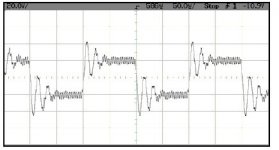
I tested with 220nF capacitive load, and output is similar to this (the figure is extraced from an IcePower 250ASP module from B&O):
What most worries me is the ringing with a power resistor (that must have some inductance, of course).
Is there something more that I can do to improve phase margin?
20 uH + 440nF
4.7uH + 220nF
Then a zobel network (120nF in series with 18 ohm/2W)
The feedback is taken from the output of the first stage (second LC filter not included into loop).
I tested with 220nF capacitive load, and output is similar to this (the figure is extraced from an IcePower 250ASP module from B&O):
What most worries me is the ringing with a power resistor (that must have some inductance, of course).
Is there something more that I can do to improve phase margin?
Attachments
I have to check...
BTW: How can modulation depth affect estability? Loop gain is fixed and determined only by supply rails and triangle amplitude, isn't it?
BTW: How can modulation depth affect estability? Loop gain is fixed and determined only by supply rails and triangle amplitude, isn't it?
BTW: How can modulation depth affect estability? Loop gain is fixed and determined only by supply rails and triangle amplitude, isn't it?
The loop stability is not only subject to phase-marging but also to the Nyqvist criterion (as mentioned before). The sample-rate of a carrier-based PWM amp is twice the switching frequency if no input signal is present (i.e. two decisions per cycle !!). For 100 % modulation it is equal the switching frequency because the two instants where the switching decision is taken move together in time.
So there is definitely some dependancy of stability on output voltage.
Your second output filter has quite a highish Q. Depending on the load connected to it many things can happen. It would be wise to dampen its Q a little by the use of a parallel resistor to the coil and by using a lower-valued cap than present. If you care about the carrier suppression you can still add a parallel cap to the coil in order to generate a notch.
Regards
Charles
In fact I had a notch before, but there is something I don't like about it: although carrier supression is excellent, attenuation at higher frequency (after the notch) corresponds to a classic 2nd order LC filter. With a 4th order filter, att. at 100MHz is around 90dB higher, which is very good for RFI interference reduction.
Thanks for the clarifications. Will try and tell you the results...
Thanks for the clarifications. Will try and tell you the results...
I played a bit yesterday. Generated an inductive load by adding a 47uH inductor in series with my load. Inmediately quite a bit of ringing appeared at high power levels, much more than with the resistors only.
Then I played a bit, and found that with the simple addition of a heavier zobel network (5 ohm + 330nF) all disappeared and now the waveform is quite clean. (Before, I had 120nF + 18 ohm).
(I was also looking at an "old" B&O Icepower 500A that I had at hand, and found that its snubber is 5 ohm + 820nF. The resistor is a TO220 package, and from my simulations it has to dissipate above 30W at 20KHz full power!!! That explains the limited high frequency audio it can deliver continuously as said in the datasheet)
I was also looking at an "old" B&O Icepower 500A that I had at hand, and found that its snubber is 5 ohm + 820nF. The resistor is a TO220 package, and from my simulations it has to dissipate above 30W at 20KHz full power!!! That explains the limited high frequency audio it can deliver continuously as said in the datasheet

 😱
😱  🤐
🤐The cut of off your zobel should be higger than the max frequency respond of your amplifier. The frequency should be limited at the input with lo pass filter. The maximum frequency response of you amplifier itself (without input filter) should be at a maximum of 1/2 the carrier frequency. That's a general rule I have found for stability. Good value I use in all my amplifier is 47uH for the first filter with .47uF, a 15 ohms and .22uF for the snubber, a 12K ohms feedback with 47pF and an input filter at 25Khz at 18Db. Switching frequency at 250Khz, and everything is always completly stable, even at 2 ohms. A trick here to avoid rigging, keep the gain of the power stage low (by the feedback) and drive the power stage with higger level....
Fredos
Look at this schematics for your feedback...
http://www.diyaudio.com/forums/showthread.php?s=&threadid=69349&perpage=10&pagenumber=4
www.d-amp.com
Fredos
Look at this schematics for your feedback...
http://www.diyaudio.com/forums/showthread.php?s=&threadid=69349&perpage=10&pagenumber=4
www.d-amp.com
By the way, It seem that is the only treads who talk about real power amp, not only the use of already build commercial amplifier...Why other guy who whant to ''make'' a class d amplifier use only prebuilt amplifier or kit??? That disapoint me that no much people try the real thing! Not the good way to improve something!
A bit sad...
Ferdos
A bit sad...
Ferdos
Thanks, Fredos, for sharing your schematics. I will have a deeper look at it this afternoon.
Charles, why are you so puzzled? Yes, believe me, they limit the maximum time you can run high frequency signals. If I recall ok, you can run at 10KHz for no longer than 1 seconds without triggering their "hf protection" circuitry 😀 😀 😀 , and they recognize that limitation comes from the zobel only!
Charles, why are you so puzzled? Yes, believe me, they limit the maximum time you can run high frequency signals. If I recall ok, you can run at 10KHz for no longer than 1 seconds without triggering their "hf protection" circuitry 😀 😀 😀 , and they recognize that limitation comes from the zobel only!
Mmmmm. It is difficult to download the demo version of Circad. Don't you have that shematics in JPG, PDF or other more viewable format?
BTW: You propose to have lower gain for estability; but lower overall gain implies higher feedback level, higher loop gain, that intuitively means more chances of inestabilities, doesn't it?
Thanks!
BTW: You propose to have lower gain for estability; but lower overall gain implies higher feedback level, higher loop gain, that intuitively means more chances of inestabilities, doesn't it?
Thanks!
I have try to convert to jpeg or pdf, but resolution came very bad...My amp use analog feedback (after the output filter) and all error correction is done in ''analog'' way. So lo gain means stability and good phase margin!
Thanks for the question!
Sorry for circad, I have no control on their web site! But it was on my ideas, the best simple PCB and SCH software!
Thanks for the question!
Sorry for circad, I have no control on their web site! But it was on my ideas, the best simple PCB and SCH software!
I think I just catch what you means...The open loop gain of the amplifier is quite hight anyways, just the closed loop gain is lo...
Think that will satisfed your question...
Fredos
Think that will satisfed your question...
Fredos
- Status
- Not open for further replies.
- Home
- Amplifiers
- Class D
- some question about IR2110