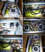
Finally got some pics of the inside,
As you can see I used two rather large torodial transformers, one/channel. Aparrantly thats better than sharing the same powersource for both channels.
I went with the one chip idea, and I think it sounds quite well, eventhough I can't say i had alot of experience with DIY amps.
I bought the enclosure from www.elfa.se
I'm still pussled where to aply the fuses. On + and - and ground, or just on + and - .
If anybody knows how to tweak it a little, (like putting som small caps here and there or something like that) I'm all ear.
I Used 2 filtercaps a powersource, rated at 6800 microF, is that enough?
Best Regards,
Christian V
Christian has attached this image:
Attachments
Your amp looks good!
On your question about fuses, I assume you're talking about rail fuses on the secondary side. If so, then you want one on each + and - rail (2 each since you have 2 transformers). These are to protect the transformer's secondary from a downstream short circuit. I use fast blows here. I'm not certain about your circuitry, and consequently I don't know what your current load is. If for example, you expect the amp to deliver 4 amps continuous, you might want to use 4 or 5A fast blows. It's probably best, when without test equipment or a variac, to start low and work your way up in amperage ratings if the fuses keep blowing. No fuse is needed in the ground leg.
You might want to also include one fuse coming into the primary side (one will do even with 2 transformers), to protect your house against one of the transformers shorting out and causing a fire. Here I use slow blow fuses. In the above scheme with 4A/channel or 8A in stereo, you might want to use a 7A slow blow; if it frequently goes, then up it to 10A.
As for the capacitance, you have about 14,000 per channel, which isn't bad. Again, since I don't know the output of your amp, I can't say for certain. Some builders have recommended x microfarads/watt of output (I recall Sloan or Self in their amplifier book giving a formula). I tend to put as much, up to about 100,000 max per channel, that I can fit into my box. Usually, I end up with 30 to 50,000 per channel. The larger your voltage, the larger the caps get, thus size can be limiting factor. (On that note, make sure the voltage rating of the caps is larger than your PS: if you're running +/- 45 VDC rails, I'd use 50 to 63VDC rated caps; 100VDC would be OK, but then you trade off size versus capacitance at the greater voltages.)
In looking at your photos, I'd be careful about adding more capacitors as you might short out your output terminals if you aren't careful. BTW, are your caps fixed somehow to ensure they won't 'roll' into the output terminals?
I hope this helps. Good luck!
Filter Caps
Are those ERO filter caps for the large power supply caps? As a heads up, I would remind all that mounting screw at the bottom
of the caps is usually connected to the negative terminal of the
cap. It must insulated when mounting to a conductive surface. I nearly got burned by this and am old enough to no better! Nice job on the amp.
H.H.
Hi,
I measured the heads on the filtercaps, and it seems they are not inductive to any of the power terminals.
I would use higher rated caps, but I can't solve the problem with the amp running on the power from the caps for a while,
when I juste switched it off.
/Christian
I measured the heads on the filtercaps, and it seems they are not inductive to any of the power terminals.
I would use higher rated caps, but I can't solve the problem with the amp running on the power from the caps for a while,
when I juste switched it off.
/Christian
You could use this design. The DC-protection part of the circuit could be eliminated, so that the amp just has loss-of-AC protection.Christian said:I would use higher rated caps, but I can't solve the problem with the amp running on the power from the caps for a while,
when I juste switched it off./Christian
Filter caps
I don't see that the amp still playing for a bit after the ac is switched off is a problem. Almost all amps do this with no ill effect since the filter caps will stayed charged until the bias current of the ouput stage discharges them. The more fiter capacitance the longer the amp will play. You could mute the signal to the input and the amp should power down silently or with a small turn off thump. This really is not a problem. For some very good info on large electrolytic caps I would go to www.faradnet.com. I still urge caution in mounting theaded lug type caps. The negative terminals on my RIFAs is connected to the mounting lug. I would read the data sheets and ap notes before mounting the caps. A few minutes online could save you a blown rectifier brige or damaged transformer.
I don't see that the amp still playing for a bit after the ac is switched off is a problem. Almost all amps do this with no ill effect since the filter caps will stayed charged until the bias current of the ouput stage discharges them. The more fiter capacitance the longer the amp will play. You could mute the signal to the input and the amp should power down silently or with a small turn off thump. This really is not a problem. For some very good info on large electrolytic caps I would go to www.faradnet.com. I still urge caution in mounting theaded lug type caps. The negative terminals on my RIFAs is connected to the mounting lug. I would read the data sheets and ap notes before mounting the caps. A few minutes online could save you a blown rectifier brige or damaged transformer.
I'll probably fuse the secondaries also, as you say.
I juste have one more question. Why is it so important to have much more powerfull transformers than your maximum output effect.
My friend recommended those 250 W torodials that you can see on the picture, but do they relly sound better then just one 80W transformer that powers both channels.
Does this have anything to do with the so called dynamic effect?
Any answers are very welcome!
Best regards,
Christian
there's a number of reasons why a bigger transformer is usually better....
*Regulation - bigger transformers usually have less difference between the loaded and unloaded voltage.
*Efficiency - A linear power supply with a transformer, bridge rectifier, capacitor bank etc has an efficiency of around 50%
*Heat - the more power you draw from a transformer, the hotter it gets and the more voltage drop that occurs within it further decreasing efficiency and producing rails that sag badly under load.
Two quick comments:
Never fuse ground.
There's no reason not to have a circuit that plays on for a bit after the amp's been shut off. I used to have .25 F on my subwoofer amp. It would play on for something like a minute before finally going to sleep. Considering that it was a 250W/ch class AB monster, that took some doing.
Grey
- Status
- Not open for further replies.
- Home
- Amplifiers
- Solid State
- Some inside pics, pretty much done