Hi there, I'm planning my first project and there are a few things I am unsure of with regards to power supplies and grounding. I'm hoping someone wouldn't mind having a look at the diagram I have attached below of how I currently believe I will power two LM3886 boards which will power two sub's.
Please note that I am new to this, so my main concern is safety. I can focus on reducing noise and optimising performance once I have familiarised myself with the equipment, and I'll try to keep this short and sweet.
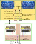
1. Using two switching supplies in series to create a +/- supply, can I directly connected this common ground (0v) to earth? Or do I Have to have a separate wire going to the amplifier housing?
2. Do I need a ground break/disconnecting circuit? I would like to keep it legal for the UK.
3.a. Is this how I would implement a CLC filter? I.e. do the values look plausible?
b. Is this where I would place the load resister (and LED to show charge in the caps)
c. Can I use an inductor that has an amp rating 3 times the max output of the supplies?
d. Does it matter if I have the filter circuit within the amp housing, a fair distance away from the PSU housing?
4. Finally, I have noticed in alot of people's diagrams that they connect the speaker ground directly to the star ground instead of the PCB output ground, is there a reason for this?
Sorry I know these are very basic questions that have been covered in one way or another, but everyone seems to do it differently and claim they are correct. I would rather ask and look stupid than risk blowing myself or the equipment up, I haven’t been able to find much information with regards to using SMPS.
Thanks in advance for your time and input.
Please note that I am new to this, so my main concern is safety. I can focus on reducing noise and optimising performance once I have familiarised myself with the equipment, and I'll try to keep this short and sweet.
1. Using two switching supplies in series to create a +/- supply, can I directly connected this common ground (0v) to earth? Or do I Have to have a separate wire going to the amplifier housing?
2. Do I need a ground break/disconnecting circuit? I would like to keep it legal for the UK.
3.a. Is this how I would implement a CLC filter? I.e. do the values look plausible?
b. Is this where I would place the load resister (and LED to show charge in the caps)
c. Can I use an inductor that has an amp rating 3 times the max output of the supplies?
d. Does it matter if I have the filter circuit within the amp housing, a fair distance away from the PSU housing?
4. Finally, I have noticed in alot of people's diagrams that they connect the speaker ground directly to the star ground instead of the PCB output ground, is there a reason for this?
Sorry I know these are very basic questions that have been covered in one way or another, but everyone seems to do it differently and claim they are correct. I would rather ask and look stupid than risk blowing myself or the equipment up, I haven’t been able to find much information with regards to using SMPS.
Thanks in advance for your time and input.
Attachments
I'm sorry, what do you mean?Is this another direct to mains project?
Most of the circuitry inside the SMPS is directly connected to the mains electricity supply.
Is your project looking at opening up, or modifying the insides of, the SMPS?
Is your project looking at opening up, or modifying the insides of, the SMPS?
Thanks for the reply Andrew, I do not have alot of experiance with electronics so I do not want to do any major modifications to the SMPS's but I will be opening them up.
As I understand it, in order to connect them in series I have to check that the neg/com outputs of each supply are not internally earthed which would cause a short? In which case I would assume I could not directly connect the created common ground of the two supplies to earth, but I have seen vague referances to it being done this way. This is about all of the information I could find on using these kind of supplies.
Is this what you are referring to?
Again many thanks
Thanks for the reply Andrew, I do not have alot of experiance with electronics so I do not want to do any major modifications to the SMPS's but I will be opening them up.
As I understand it, in order to connect them in series I have to check that the neg/com outputs of each supply are not internally earthed which would cause a short? In which case I would assume I could not directly connect the created common ground of the two supplies to earth, but I have seen vague referances to it being done this way. This is about all of the information I could find on using these kind of supplies.
Is this what you are referring to?
Again many thanks
if just to check that the negative side of the dc rails is not connected to chassis, we can allow that, provided that you are not plugged in to the wall...please put away the power cord for the time being...
you are correct, if you want to series connect smps psu's make sure that the negative side of the dc rails are isolated, this is easy to do...
remember, safety first....
Indeed, safety first. I am not buying any of the equipment untill I am certain I can build it safely.
However I have decided to go for a TK-2050 based amp instead so I can use a single power supply and keep it simple/small.
Would either of you mind answering the other questions from the top? Sorry to be a pain but I do not need detailed answers, mainly just yes/no's.
I greatly appreciate your time
However I have decided to go for a TK-2050 based amp instead so I can use a single power supply and keep it simple/small.
Would either of you mind answering the other questions from the top? Sorry to be a pain but I do not need detailed answers, mainly just yes/no's.
I greatly appreciate your time
Remove C4.
Remove the label saying star ground. It is your Chassis connection. The Earth connection will be quite separate and bedise the incoming mains power cable.
Make the green wire junction between the two PCBs your Main Audio Ground.
Read the various Threads about modifying the XY PCBs.
Remove the label saying star ground. It is your Chassis connection. The Earth connection will be quite separate and bedise the incoming mains power cable.
Make the green wire junction between the two PCBs your Main Audio Ground.
Read the various Threads about modifying the XY PCBs.
- Status
- Not open for further replies.
- Home
- Amplifiers
- Power Supplies
- Some brief questions on SMPS's filtering and grounding