No. A p-jfet works in depletion mode. So the source has to be biased negative with respect to the gate (which is at DC ground). If the grid is grounded and the cathode is negative, that will be a Bad Thing.
The gate has to be biased positive in respect to source, not source! That means, if we ground gate of P-type JFET follower voltage on it's source will be negative.
Once again: I mean a source follower on P type JFET.
Anatoliy, if the gate is at DC ground, the source has to be negative, right?
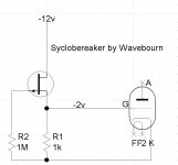
No. For P-type JGFET source have to be positive. Just one JFET, one resistor. Negative power source for the drain, negative voltage drop on the resistor between source and ground, applied to the grid.
Edit: if you want to use N-type JFET, just stick it in cathode, grid to ground, and get cascode.
Last edited:
Absolutely doable (and commonly done). Not cheap. You have to provide ultra clean power since the power supply rejection is near zero. You have to take great care not to abuse heater-to-cathode ratings.
My last phonostage was a cascode (NTE458 on the bottom, 12V version of ECC88 on top) which took a lot of patience to get right.
My last phonostage was a cascode (NTE458 on the bottom, 12V version of ECC88 on top) which took a lot of patience to get right.
Thanks SY. After posting I decided to google cascode phono and found many examples. None buffered the eq. though so maybe the highish Zout is not as big of deal as I first thought.
As to PS cost I see a couple of options; one involving some relatively expensive chokes and another using rather cheap sand. The solid state regulator approach would seem to be the most apropos for the OPs situation. Given the rather good gain of a cascode maybe one could use a rather low rp triode and thus keep the impedances in check.
Am I right that the cascode provides much of the pentode advantages without the noise?
You're indeed right. No partition noise. Low rp won't help you, though- the PSR is almost completely independent of tube parameters and is close to zero.
If memory serves, Conrad Johnson followed the cascode with a buffer in some of their preamps, but I could be wrong about that. I think it's a good idea- it means the tube is always operating into a pure resistive (and constant) load.
If memory serves, Conrad Johnson followed the cascode with a buffer in some of their preamps, but I could be wrong about that. I think it's a good idea- it means the tube is always operating into a pure resistive (and constant) load.
One last comment and then I will return you to your regularly scheduled programming. For kicks I downloaded Steve Bench's cascode stage gain calculator and ran some numbers on the 6N1P and it looks to me like getting 40dB gain from a single cascode stage is quite doable making the need for a second stage (other than buffering) somewhat suspect though I suppose there might be some benefit to adding a second low gain stage just so that you can separate the bass turnover from the treble one.
One last comment and then I will return you to your regularly scheduled programming. For kicks I downloaded Steve Bench's cascode stage gain calculator and ran some numbers on the 6N1P and it looks to me like getting 40dB gain from a single cascode stage is quite doable making the need for a second stage (other than buffering) somewhat suspect though I suppose there might be some benefit to adding a second low gain stage just so that you can separate the bass turnover from the treble one.
You are fogetting that RIAA EQ, passive or active, imposes a 20 dB. loss at 1 KHz. A NET gain of 45 to 50 dB. is what's needed with a "typical" MM cart. So, the 2nd gain block is absolutely essential.
Wow fellows! I had lots to chew on well before you really went at this decent phono-stage on a budget problem.
Thanks for not giving up on me Wavebourn! but his thing has gone WAY WAY ABOVE my pea-brain...so it's back to more readin', researchin' doodlin' and head scratchin'
Thanks again everyone...never imagined this was going to be so complex! But I'm certain it will inevitably be rewarding......Leo
Thanks for not giving up on me Wavebourn! but his thing has gone WAY WAY ABOVE my pea-brain...so it's back to more readin', researchin' doodlin' and head scratchin'
Thanks again everyone...never imagined this was going to be so complex! But I'm certain it will inevitably be rewarding......Leo
if can ask a possibly stupid question, what is the function of the OPA2134 in the practical pre-amplifier? i have read the (great) book and i couldnt see it. Is there an alternative, i assumme that its current or voltage control.For MM, figure $400-500 or thereabouts. MC, add a few hundred.
The "Practical Preamplifier" shown in Morgan Jones's "Valve Amplifiers" is a reasonably good circuit for the lower end of these costs. It doesn't use 12AX7.
- Status
- This old topic is closed. If you want to reopen this topic, contact a moderator using the "Report Post" button.
- Home
- Amplifiers
- Tubes / Valves
- Some agreement on reasonable affordable and well performing design builds?