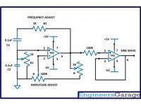
So I am trying to create a sine wave generator that puts out 440HZ at 1v. I came across this circuit but how would I solve for R1,R2,C1,C2 given the equation for frequency? If it were just one variable it would be simple but four variables is troubling me to say the least. I do not understand the relations enough to solve this. Thanks for any help.
Attachments
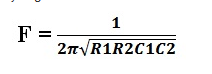
Simple transformation of formulae. We learnt it at school when I was 12. Find the value of F.
If you weren't taught it, your school wasn't very thorough, use your computer to gargle it.
transformation of formulae - Google Search
If you weren't taught it, your school wasn't very thorough, use your computer to gargle it.
transformation of formulae - Google Search
I can solve the equation but do not know the relationship between the 4 variables. And.....I will not be solving for F Iit is 440hz. I am solving for R1, R2, C1, and C2.
You know every time I post anything on here you post a snide comment. Perhaps you should stop the drinking and actually understand what I am asking for assistance with before you put your foot in your mouth once again. I feel so sorry for the people around you.
You know every time I post anything on here you post a snide comment. Perhaps you should stop the drinking and actually understand what I am asking for assistance with before you put your foot in your mouth once again. I feel so sorry for the people around you.
Last edited:
You need to make choices, because a single equation isn't sufficient to solve for everything.
One option is to make R1=R2, C1=C2 as in the example, with values suitable for the opamp impedance, bias, etc.
This will result in a gain of 1/3, which will require the amplifier for providing it.
Other components ratios will result in different gains.
For example, if R1=2R2 and C1=2C2, the gain will be 1/2
You have to make sure R1, R2, C1 and C2 have sufficiently low impedance compared with the impedances of the opamp's inputs. A factor of 10 is used for transistor biasing potential dividers and should work with this setup. Make sure, the resultant impedance does not overload the opamp's output at the working frequency.
As written before this post, in this network, R1 is set to equal R2 and C1 to equal C2. To get sustained oscillations, you will need a gain that is slightly greater than 3. This oscillator is known as Wien Bridge oscillator.
The impedance, Z of the network is:
Z = series_part + parallel_part
Z = R2 + Xc1 + R1 || Xc2
To evaluate the above, you can either use complex number notation and derive an expression for the complex impedance, or better, use a phasor diagram. You can split the phasor problem in two. First find the phasor for R2 + Xc1 followed by the R1 || Xc2. Then, use a another phasor diagram for the two resultant phasors keeping in mind the current in BOTH impedances is equal in phase and value. This allows you to decide the angle between the resultant phasors for the final calculation.
Instead of using trigonometry to solve the phasors, you can resolve them into two perpendicular components, add the components and use the results to solve a right angled triangle.
Last edited:
Since one resistor of the Wien Bridge is in parallel with one input, you may assume, the opamp's input impedance is 100k. To get an impedance ten times less than this, you can choose R = R1 = R2 to be 10k. The reason for this is to make sure the input does not disrupt the functioning of the Wien Bridge. Since, you have a series-parallel bridge, we can assume, the impedance of the bridge is 10k at a minimum (Please, check the last assumption, as my logic may be rusty out of age, and the long passing of decades since I did this.). With that, we have one resistance known:
We can follow to calculate the capacitance required at 440Hz.
The formula is f = 1/(2*pi*sqrt(R1.C1.R2.C2))
Putting, R1 = R2 = R = 10k and C1 = C2 = C, we get:
f = 1/(2*pi*sqrt(R^2.C^2))
=> f = 1/(2*pi*R*C)
=> 2f*pi*R*C = 1
=> C = 1/(2f*pi*R)
With f = 440Hz and R = 10k, we get:
C = 1/(2*440*3.142*10000)
C = 36nF
Let us consider the output being loaded with this network. Assuming a minimum impedance of 10k and a rail voltage of 15V, we can find the peak output current in the network.
Peak Current ~= 15/10000 = 1.5mA (assuming an output voltage sweep from +rail to -rail.)
Please note, that to get a 1V output peak you will need to use a potential divider. You may also require the use of non linearity in the network to force it to oscillate within the voltage range you want it to. To get that you may use two signal diodes across the input connected to the network.
P.S.
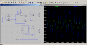
Simulating on LTSpice shows you have to use non linearity to limit the amplitude of oscillation. Two signal diodes across the non inverting input gives a much better sine looking waveform. With diodes added you will know the amplitude of the output signal permitting you to get a 1V output as you wish.
We can follow to calculate the capacitance required at 440Hz.
The formula is f = 1/(2*pi*sqrt(R1.C1.R2.C2))
Putting, R1 = R2 = R = 10k and C1 = C2 = C, we get:
f = 1/(2*pi*sqrt(R^2.C^2))
=> f = 1/(2*pi*R*C)
=> 2f*pi*R*C = 1
=> C = 1/(2f*pi*R)
With f = 440Hz and R = 10k, we get:
C = 1/(2*440*3.142*10000)
C = 36nF
Let us consider the output being loaded with this network. Assuming a minimum impedance of 10k and a rail voltage of 15V, we can find the peak output current in the network.
Peak Current ~= 15/10000 = 1.5mA (assuming an output voltage sweep from +rail to -rail.)
Please note, that to get a 1V output peak you will need to use a potential divider. You may also require the use of non linearity in the network to force it to oscillate within the voltage range you want it to. To get that you may use two signal diodes across the input connected to the network.
P.S.
Simulating on LTSpice shows you have to use non linearity to limit the amplitude of oscillation. Two signal diodes across the non inverting input gives a much better sine looking waveform. With diodes added you will know the amplitude of the output signal permitting you to get a 1V output as you wish.
Attachments
Last edited:
C1=C2=100nF would be a typical value for 440Hz, and solving the equation gives R1=R2=3.61K.
On the other hand, does it have to be the very schematic you posted?
It would be rather tricky to adjust and the output voltage won't be stable.
As an alternative, you might like to have a look at this:
OP-AMP COOKBOOK — Part 3 | Nuts & Volts Magazine
My recommendation is the oscillator of Fig. 5, but mind the error in the schematic: C2 must also be a 100nF part.
Since you're interested in a single frequency, the 10K pot in the above schematic could be replaced by a ganged 2x500 ohm potentiometer in series with a 3K3 resistor.
Applying the equation for frequency, you can then easily calculate the adjustment range.
Hope this helps.
Regards,
Braca
And the '741 is not the opamp to choose (unless its the 1970's but even then there were
much better choices).
A decent modern audio opamp is a good choice for an audio oscillator - low distortion, low noise.
much better choices).
A decent modern audio opamp is a good choice for an audio oscillator - low distortion, low noise.
- Home
- Design & Build
- Construction Tips
- solving equation for frequency