below is a link to a solid state rectifier and I wanted to get your thoughts on something that they warn you about with this rectifier.
https://tubedepot.com/products/solid-state-rectifier
The warning on the above website is the following;
"Note: Please be advised that this replacement will increase overall B+ (plate voltage) by 10-20%. If your filter caps are older than 20-25 years, we suggest you replace them before installing this solid state rectifier."
1) can that higher plate voltage (higher overall B+) damage or shorten the life of any parts in a Dynaco VTA ST-120?
2) is there any modification or change that you'd recommend should be done to the ST-120 before plugging in this SS rectifier?
3) would this SS rectifier make it advisable to change the bias target from 550mV to some other number?
4) what other adverse results might be experienced as a result of using the above SS rectifier?
thanks,
Eddie
Its mainly the increase in B+.
You also have to bear in mind before heaters warm up that the B+ will b higher than normal.
You need to work out the B+ and see if all your valves will stand the higher voltage.
I designed a valve amp with ecc83 on the front end but with a RC voltage dropper from the output valve B+. It was possible on power up for the B+ to be out of spec for the ecc83.
simple solutions
if you want to knock it back down a little bit, you can add a MOSFET as though you were regulating the voltage, but attach the gate to the source with an appropriate resistor and the appropriate diode for protection. You can also add a choke and that will knock a few volts off. I have converted quite a few amps from tube rectifier to solid state. Sometimes the B+ goes WAY up and sometimes it only goes up a little.
Nelson Pass has a great, simple solid state voltage regulator on his site. You can easily modify it for a tube amp. The advantage is that the sound will be cleaner, noticeably cleaner. The bass will be firmer. The highs will "shimmer" more. I was so pleased with the improvement that I retrofitted with solid state regulators for preamp section and the above-mentioned MOSFET filter for the power tubes. If you run the voltage regulator without the reference voltage on the gate of the transistor, it will still filter, like a choke, but won't regulate. It does firm up the sound though, and is a noticeable improvement.
You can use the solid state rectifiers, it moves the B+ up a bit and may be pushing the edge of the filter caps.
Look for the Weber Copper Cap WZ68 I think that will do the trick for your ST-120.
You must reset the bias on the amp as the voltage may be higher then with the GZ34 but you will have to find the new plate voltage just to double check and do the setting.
If you do use the solid state replacement rectifier from the Tube Depot, you should definitely check the plate voltage just to make sure what it is. The primary capacitor I think is rated at 525v on the ST120 if I remember correctly and I can't remember what it was when I tried it (I have the tubedepot one as well).
http://www.webervst.com/ccap.html GZ68 is what I'm running
Sandy
Last edited:
Electrolytic caps can get used to whatever voltage is usually across them. For example, a 450V cap which usually sees only 300V will gradually (over a few years) become a '300V' cap. Any circuit change which will put a significantly increased voltage across it may mean that it needs to be reformed to the higher voltage, even if this voltage is well within its original specification. A 10% increase may be OK and may simply mean increased leakage current for a few hours. Best to use a lamp limiter and check for any cap overheating.
Shouldn't Mr. Latino answer your questions? It seems the SS rectifier mod for the Dynaco is very common, and easily implemented:
Mr. Latino's comment on the same thread, seems to indicate that the capacitors in the ST-120 should be able to handle it, no idea if the bias needs to be adjusted...
Mr. Latino's comment on the same thread, seems to indicate that the capacitors in the ST-120 should be able to handle it, no idea if the bias needs to be adjusted...
a lamp limiter is best to use if you plug in that rectifier, just so you have peace of mind....
another thing i do is to add two 27 ohm to 47 ohm 5 watt resistors in series with the hv windings going to the plate of the rectifiers, you lose B+ this way...
another thing i do is to add two 27 ohm to 47 ohm 5 watt resistors in series with the hv windings going to the plate of the rectifiers, you lose B+ this way...
This whole discussion is *****-****. Bob Latino doesn't make or sell Dynaco amplifiers. The ST120 is a transistor amplifier. I own one. I also own a ST-70 Dynaco tube amp. Change the title of the thread or delete yourself, IMHO.
In the ST70, B+ capacitors lasted about 8 years. I replaced the quad 4 times in 40 years, with a long gap 1982-2010 when I couldn't buy output tubes. But the B+ cap deteriorated sitting in the storage room; I got 4 hours service life out of it before it leaked and blew the fuse in 2010.
Solid state B+ rectifiers hammer cold tubes with fast B+ before they are ready. If you do this, be sure to put a CL-90 or similar NTC resistor in the 120 VAC power supply to provide a soft start. Read various sources about cold stripping, and decide for yourself if you want to experiment with a $120 tube set when an $18 5AR4 would solve any potential problem. Or a $2 NTC resistor.
Last edited:
I agree with indianajo. The tube rectifier gives a nice soft start and a delay which allows the tubes to heat up before getting full B+ voltage, extending their life.
A NTC would protect the rectifiers and the capacitors against inrush, but not the tubes.
I always use a delay circuit to turn on B+ after at least 30 seconds of heating, in my solid-state rectified amps.
A NTC would protect the rectifiers and the capacitors against inrush, but not the tubes.
I always use a delay circuit to turn on B+ after at least 30 seconds of heating, in my solid-state rectified amps.
This is not a solid state rectifier mod. This is for adding protection diodes to the existing tube rectifier.
Shouldn't Mr. Latino answer your questions? It seems the SS rectifier mod for the Dynaco is very common, and easily implemented:
Mr. Latino's comment on the same thread, seems to indicate that the capacitors in the ST-120 should be able to handle it, no idea if the bias needs to be adjusted...
This whole discussion is *****-****. Bob Latino doesn't make or sell Dynaco amplifiers. The ST120 is a transistor amplifier. I own one. I also own a ST-70 Dynaco tube amp. Change the title of the thread or delete yourself, IMHO.
Bob Latino makes and sells Dynaco clones and uses the confusing "VTA ST-120" model name for his version of the beef-up Dynaco ST-70. This is the amp that the OP bought and are having trouble with.
Bob Latino makes and sells Dynaco clones and uses the confusing "VTA ST-120" model name for his version of the beef-up Dynaco ST-70. This is the amp that the OP bought and are having trouble with.
There is nothing Dynaco cloned in that amp.
There is way too much Dynaco name "coopting" in the cottage industry of DIY Dynaco aftermarket.
Putting a different circuit on a similar designed steel box (he says his box is better engineered) doesn't give anyone the right to brand themselves "Dynaco." There are plenty of newbies who don't know what's, what. They just want a piece of the fun, and will buy into the fog of the hobby and keep the misnomers propogated.
20
Last edited:
If the OP's amp is indeed a Bob Latino one and it is wired the same as these:
Bob Latino Dynaco Tube amps
Scroll down for the pics.
I would strongly suggest fitting 3 wire mains lead. Also the other two howlers are pretty obvious. The mains switch and fuse!! These should both be in the live conductor preferably fuse first and if possible a double pole switch.
Shocking!!!!!!
Cheers
Matt.
Frank Van Alstine and Dave Curcio are two guys modding the Dynaco ST70 and have been using the Dynaco trademark, are there legal impediments to this?
Not that I can see (though IANAL)- their stuff is for actual Dynaco amps. It's like selling aftermarket mufflers or modified camshafts for Fords.
a lamp limiter is best to use if you plug in that rectifier, just so you have peace of mind....
another thing i do is to add two 27 ohm to 47 ohm 5 watt resistors in series with the hv windings going to the plate of the rectifiers, you lose B+ this way...
here 100R 5 watts,........kuya
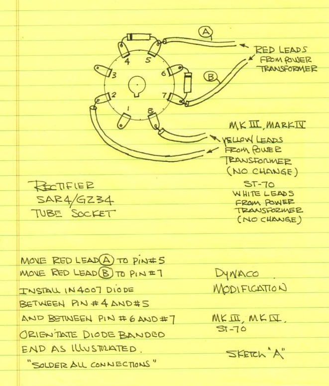
Poor man's solid state replacement rectifier for Dynaco ST-70, Mark II, Mark III or Mark IV
I can't see where he mentioned capacitors at all, but as his mod reduces B+ by ~0.5V there is no apparent reason why the PSU capacitors shouldn't handle it, or the bias should need adjustment either.Mr. Latino's comment on the same thread, seems to indicate that the capacitors in the ST-120 should be able to handle it, no idea if the bias needs to be adjusted...
Again, this mod is not a rectifier replacement by SS, it just the addition of series SS diodes, apparently to protect valve rectifiers that don't meet their PIV specification. My solution would be to use a rectifier that is within spec.
First: using SS rectifier will increase power dissipate over output tubes; means shorter life of output tubes.
Second: installing resistors in series with SS rectifiers will sag voltage exactly as tube rectifier does. So, installing SS rectifier is not good. You can use different power transformer or use tube rectifier. Or use a variac to reduce ac input voltage.
Second: installing resistors in series with SS rectifiers will sag voltage exactly as tube rectifier does. So, installing SS rectifier is not good. You can use different power transformer or use tube rectifier. Or use a variac to reduce ac input voltage.
- Status
- Not open for further replies.
- Home
- Amplifiers
- Tubes / Valves
- Solid State Rectifier in Dynaco Tube Amp