For what it's worth I can tell you what I think... absolutely the best 🙂
Based on listening to many amps over the years 😉
Hi Mooly,
Mr. Borbely says the same and I am beginning to think the same too. Because this I asked to PMA about what he feel on lateral mosfets at output instead bipolar transistors no ragarding price, SOA, etc.....only SOUND QUALITY !
I know this question could belongs to another thread but I wonder if there is a chance to upgrade the sound in his new amplifier.
Thanks
eD
Last edited:
About Bode plots again
Quote from PMA webpage:
"It is a loop-gain, not open-loop gain"
Plots are the same as these in ansfer for my request.
These plots looks as open loop plots, so v(out1)/(R58/R10+1).
In that case amplifier has about 26db feedback at 20kHz.
And at 400kHz there is zero crossing, so about 60deg
phase margin. And little above 1MHz 10dB gain margin.
Then why plots labels says v(out1)?
Is there just 6dB feedback at 20kHz and so on?
I am just little confused
Last edited:
This amplifier was inpsired by conversation with John Curl in a ‘Blowtorch thread’, as well as by his thoughts ( www.parasound.com/pdfs/JCinterview.pdf ).
The aim was to build a reliable, solid, good sounding amplifier.
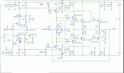
Topology is complementary differential, with JFET input, MOSFET cascode and VAS, and BJT multiple pair output stage. The circuit shown might be an inspiration for DIYers in their designs.
A functional sample was build, the circuit is very stable and rugged.
The project is not a commercial project, no PCBs or kits will be sold.
Just to steal 🙂 PMA's design I post a modified design.
The main change is the lost of the input differential.
This way the amplifier becomes (IMHO) a current feedback amplifier.
I have not simulated nor built such amplifier.
Is there anybody who tried this amplifier?
Which are the main advantages (and drawbacks) of this different topology?
Attachments
Just to steal 🙂 PMA's design I post a modified design.
That's funny as i had quite the same idea, inspired from F5.
Attachments

Will work, however, difficult to remove input offset. Harder to make, but more idealistic. Made first prototype in early '70's. Decided to return to comp differential jfets for practical reasons.
Hi John
Just a quick question, why mosfets as cascode devices and not bjt that perform better in these positions, this applies to the vas too, is it purely a subjective measure ???
Just a quick question, why mosfets as cascode devices and not bjt that perform better in these positions, this applies to the vas too, is it purely a subjective measure ???
Bobodioulasso and diy_audio_fo that type of circuit has been done quite long ago by the french and japanese, not sure who was first but long before the F5. The F5 is virtually a copy of the french Profet class A amp except the Profet uses lateral mosfets and doesnt have dual feedback like the F5.
getting back to pma's design ...
pma:
if you willing to share why, i'm curious why you chose not to use either a triple bipolar transistor follower output stage or use another set of the hitachi mosfets as drivers for the output bipolar devices?
thx,
mlloyd1
pma:
if you willing to share why, i'm curious why you chose not to use either a triple bipolar transistor follower output stage or use another set of the hitachi mosfets as drivers for the output bipolar devices?
thx,
mlloyd1
Hi all, I am back from my ‚holiday‘.
I would like to thank to stinius, BV, John Curl, Sendy and danhard for clarification of some technical issues and for posting images and links; and also thanks to many others for their support.
I have already answered some of the questions in my website
PA2 power amplifier
especially that concerning open-loop gain and confusion with loopgain. Both only simulated, so not necessarily same as in the real amplifier.
As you can see, I have built a functional prototype and performed some measurements.
During my holiday week, I have been listening to the amplifier. I would describe the sound as:
- overall lack of smear,
- transparent, and detailed soundstage,
- free of unnatural grain,
- the bottom end well depicted,
- bass not overdamped, not overly constrained,
- combination of speed, liquidity, transparency, and creamy purity,
- tonally neutral, detailed in the midrange,
- excellent resolution of subtle, low-level dynamic detail,
- very good imaging and space.
Solid-state amps are usually too bright and hard on top, or too soft and unfocused. This one is just about right, neither etched nor softened, but just far enough on the right side of "silky-smooth" to sound tonally natural.
I have borrowed these audio review terms from MF, many thanks 🙂
Several words on topology of this amplifier. The topology was definitely invented by John Curl, as I indicated in the first post of the thread. As posted here, it can be absolutely safely used with any speaker complex load (even 2 ohm) with supply rails 2 x 30V. Increasing rails to 2 x 50V restricts speaker complex load to 4 ohm and more. The power would be 2 x 200W / 4 ohm at 2 x 50V rails. Resistive load 2 ohm is not any issue, but complex load with real component of 2 ohm is.
It would be easy to build a ‘Big Brother’ version of this amplifier. I would suggest six pairs of output devices, and supply rails 2 x 80V. Then one can expect 2 x 400W / 4 ohm output rms power, and no worries about load type.
MJL21193/4 are extremely rugged devices, and their 1 sec, 150°C Tj(pk) SOA is amazing. The use of laterals, as proposed in this thread, would not be any sound improvement IMO, and would result in much less robust amplifier.
pma:
if you willing to share why, i'm curious why you chose not to use either a triple bipolar transistor follower output stage or use another set of the hitachi mosfets as drivers for the output bipolar devices?
thx,
mlloyd1
Personally, I do not prefer a triple follower output.
I like CFP output, but only for class A amplifiers, and this is not the case here.
Regarding mosfet drivers, this might be considered, provided that supply rails for input stage and VAS would be increased above output stage supply rails.
Thanks, Pavel for sharing and all the details.
Woud you see any drawbaks substituing A1294/C3263 as drivers and A1295/C3264 as outputs?
As i already do have them here.
Woud you see any drawbaks substituing A1294/C3263 as drivers and A1295/C3264 as outputs?
As i already do have them here.
I hope not, though I have not tried these devices. In case you are experienced, have tone generator and oscilloscope, and will start with protection series resistors (like 3 - 5 ohm/5W) and F4A fuses in supply rails, why not to try it. Let us know your results.
Thanks,
Thanks,
Woud you see any drawbaks substituing A1294/C3263 as drivers and
I have rechecked datasheets, I guess that A1294/C3263 is an overkill as a driver, I would recommend something smaller and faster.
How about A1668/C4382 ?
Last edited:
A1668/C4382 are faster but would they be sufficient to drive six output pairs @ 2 x 80 v rails?
The big brother vou mentioned.
I am far from being an expert , so i will certainly follow your advice.
The big brother vou mentioned.
I am far from being an expert , so i will certainly follow your advice.
Last edited:
To me, capacitance of A1294/C3263 as drivers is too high. Vceo of A1668/C4382 is 200V.
But, M1 and M2 are limited at 140V.
But, M1 and M2 are limited at 140V.
Last edited:
Regarding VAS transistors mentioned some time ago, the VAS collector current is set quite high. This might be an explanation why the slew rate is high even with the mosfet types used.
Please recheck my webpage, time after time I am updating the images and text.
PA2 power amplifier
Please recheck my webpage, time after time I am updating the images and text.
PA2 power amplifier
Personally, I do not prefer a triple follower output.
I like CFP output, but only for class A amplifiers, and this is not the case here.
Regarding mosfet drivers, this might be considered, provided that supply rails for input stage and VAS would be increased above output stage supply rails.
Hi PMA! Nice "classic" design.
Why you do not prefer a triple follower, is it about oscilation problems or the sound?
Cheeers!🙂
I had a question. And not the other reasons?PMA said:I will always stand out against a life threatening designs and hoax designs.
And the show's on again... PMA don't go again for another tour de vacation in the 'sunny bin'!..

Last edited:
- Status
- Not open for further replies.
- Home
- Amplifiers
- Solid State
- Solid Solid State Power Amplifier