Hello--
Am toward the final stages of layout planning for a JE Labs Deluxe 2A3 build. This is my first "from scratch" build. While I am confident in some aspects of the layout, I am curious to hear from those who have experience in amplifier layout, especially with regard to lead dress.
The "tl;dr" here is this: Which wiring must I absolutely keep as far as possible from which other wiring, especially with regard to B+/plate, filament, and signal, and which are the ones which are more or less taken care of by proper braiding and routing?
I am struggling to choose between a layout which splits the L & R channels down the middle with a power supply section and a layout which devotes half of the chassis to the power supply, and the other half to handling of the signal.
Am also interested in first-hand experience with toroids and whether there are any general rules-of-the-road for their placement. From what I have seen in searches on the internet so far, the EMI put off by toroids seems to be negligible, and what is there is emitted out of the "hole" in the middle--i.e., elements above or below the toroid may experience interference, but not to the side.
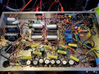
Please see the attached photos before reading further. Obviously plenty of small components are missing from the layout. I have purposely included only the largest components.
For those familiar with the circuit, I have modified the power supply to be CLCLC.
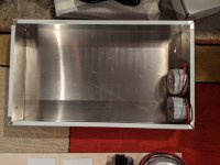
The chassis is 10x17x3 aluminum from Hammond. The general idea is to segregate all the power supply elements to one side of the chassis. The speaker output and RCA input will be mounted vertically in the chassis to the rear of the output transformers (the white squares on my layout board). The signal input would be routed left to the corner, then down, then in front of the tubes.
Please ignore the pin count of the tubes. I still have some parts to order. There will be two sets of 3 tubes for the driver & output sections, then a single rectifier. Each 2A3 will have a coupling capacitor and a chassis resistor nearby, as shown for one.
The output transformers will be mounted on top of the chassis, along with the main (toroidal) power transformer. The power TX will favor the right and back corner. Toroidal filament transformer is directly below the main TX. To the left of the filament TX are a pair of Pete Millett's DC filament supply boards.
The two black capacitors are the driver supply; the blue 100/100uf capacitor will supply the B+ and feed the driver supply.
There are two chokes oriented vertically to the right of the rectifier tube. They can be seen in the chassis photo. They will be to the right of the rectifier tube.
My main concerns are with all of the wires that are bound to cross between the DC heater supply, the OPT, and from the AC filament supply (tap off the main TX) to the 6SN7 & 76s.
I don't have the wiring laid out because it's where I am the least confident. I have figured out how to braid solid-core wire with the help of a drill, and know that tight braiding is a best practice. I also have some shielded 18AWG wire that can be used.
If shielded wire is used, where would that be best? The (relatively) high-amperage filament supplies? The high-voltage B+?
Is shielded overkill when properly braided wire is employed?
Ground wire will run from RCA input to the tubes, then between the big black capacitors, terminating at the vertical terminal strip near the rectifier tube. This will also be running near/under/over all of the aforementioned wiring which I am concerned about. Will that be a problem?
A center layout would allow me to completely avoid all of this cross-wiring anxiety, but it would also be more cramped and results in a top-plate which I think would be less preferable aesthetically. (Forgive me!)
Is there anything I don't even know I should be thinking about but am not addressing?
Really appreciate any and all comments. Thank you!
Am toward the final stages of layout planning for a JE Labs Deluxe 2A3 build. This is my first "from scratch" build. While I am confident in some aspects of the layout, I am curious to hear from those who have experience in amplifier layout, especially with regard to lead dress.
The "tl;dr" here is this: Which wiring must I absolutely keep as far as possible from which other wiring, especially with regard to B+/plate, filament, and signal, and which are the ones which are more or less taken care of by proper braiding and routing?
I am struggling to choose between a layout which splits the L & R channels down the middle with a power supply section and a layout which devotes half of the chassis to the power supply, and the other half to handling of the signal.
Am also interested in first-hand experience with toroids and whether there are any general rules-of-the-road for their placement. From what I have seen in searches on the internet so far, the EMI put off by toroids seems to be negligible, and what is there is emitted out of the "hole" in the middle--i.e., elements above or below the toroid may experience interference, but not to the side.
Please see the attached photos before reading further. Obviously plenty of small components are missing from the layout. I have purposely included only the largest components.
For those familiar with the circuit, I have modified the power supply to be CLCLC.
The chassis is 10x17x3 aluminum from Hammond. The general idea is to segregate all the power supply elements to one side of the chassis. The speaker output and RCA input will be mounted vertically in the chassis to the rear of the output transformers (the white squares on my layout board). The signal input would be routed left to the corner, then down, then in front of the tubes.
Please ignore the pin count of the tubes. I still have some parts to order. There will be two sets of 3 tubes for the driver & output sections, then a single rectifier. Each 2A3 will have a coupling capacitor and a chassis resistor nearby, as shown for one.
The output transformers will be mounted on top of the chassis, along with the main (toroidal) power transformer. The power TX will favor the right and back corner. Toroidal filament transformer is directly below the main TX. To the left of the filament TX are a pair of Pete Millett's DC filament supply boards.
The two black capacitors are the driver supply; the blue 100/100uf capacitor will supply the B+ and feed the driver supply.
There are two chokes oriented vertically to the right of the rectifier tube. They can be seen in the chassis photo. They will be to the right of the rectifier tube.
My main concerns are with all of the wires that are bound to cross between the DC heater supply, the OPT, and from the AC filament supply (tap off the main TX) to the 6SN7 & 76s.
I don't have the wiring laid out because it's where I am the least confident. I have figured out how to braid solid-core wire with the help of a drill, and know that tight braiding is a best practice. I also have some shielded 18AWG wire that can be used.
If shielded wire is used, where would that be best? The (relatively) high-amperage filament supplies? The high-voltage B+?
Is shielded overkill when properly braided wire is employed?
Ground wire will run from RCA input to the tubes, then between the big black capacitors, terminating at the vertical terminal strip near the rectifier tube. This will also be running near/under/over all of the aforementioned wiring which I am concerned about. Will that be a problem?
A center layout would allow me to completely avoid all of this cross-wiring anxiety, but it would also be more cramped and results in a top-plate which I think would be less preferable aesthetically. (Forgive me!)
Is there anything I don't even know I should be thinking about but am not addressing?
Really appreciate any and all comments. Thank you!
Attachments

Basic rules are -
Keep all wiring as short as possible.
If wiring crosses do it at 90 degrees.
Tuck heater wiring into chassis corners,12 twists per foot, you don't have to go crazy with a drill. Use a humbucker on IP heater.
If you have a double triode like a 6SN7 use the grid furthest away from the heaters for a first stage IP, for a 6SN7 that'd be pin 4.
Grid stoppers as near to the valve base pin as poss with as short a lead as poss.
Power supply as far away as poss from IP, mains tfmr at 90 degrees to OPT's.
All grounds back to ground connection of main smoothing/reservoir cap. On a ground bus heavy current like OP section first, then lower current stages with finally IP stage last.
Shielded cable connected at one end only.
There's bound to more,but that's the main ones I can think of just now. when I'm laying out an amp after siting tfmrs i lay out valve bases always keeping in mind to route IP's etc by the shortest possible route.
So, first off start with your OP stage, site it near the main PSU,short wire from OPT to PSU. Experiment turning the OP valve base till you have it so heater/filament wiring is off to one side if poss with grid/IP as near as poss to phase splitter or previous stage.
Then lay out subsequent valve bases in order of connection figuring out htr wiring as you go bearing in mind also your ground and HT connections, it's like 3D chess, a good workout for the old noggin.
Hope that helps,if you get stuck get out some scrap paper and work it out on paper first before drilling. Andy.
PS, see The Valve Wizard site,loads of great info there.
Thank you, Andy!
I hadn't thought at all about the distance between the origin of the B+ and the OPT... As it stands right now, the lead from B+ to the upper-left corner OPT would be one of the longest in the chassis. Given that the resistance of ~18AWG wire per foot is less than ~.006 Ohm, do I really need to care about that?
This is what I'm really struggling with. Obviously you would like all of your connections to be literally as short as possible. But in the real world, how much difference does that really make?
I have read the Valve Wizard's materials quite closely. They are excellent.
I hear you on doing it on paper first. Trying to go a bit further than that--my plan is to drill into this "craft" plywood I have, wire everything up, then test from there. If that proves successful, I can use the plywood as my hole-drilling-template on the real chassis.
In my experience, the most important part of a build is the signal wiring, and even then only if you live in a radio bomb like I do (I can not receive ANY AM radio in the largest market in Canada).
I use #22 for B+, #18 is fine but unnecessary.
I usually go for a symmetrical layout - PT in the middle back, OPTs rear corners like this.
Even with an SMPS in the middle of the chassis, there's no hash/hum/noise induced into the amplifier output.
I use #22 for B+, #18 is fine but unnecessary.
I usually go for a symmetrical layout - PT in the middle back, OPTs rear corners like this.
Even with an SMPS in the middle of the chassis, there's no hash/hum/noise induced into the amplifier output.
Attachments
Apply power to your toroidal transformers and lay things out approximately with your OT's. Put a meter on the primary of each transformer primary and look for induced hum (AC voltage).
The Hammond aluminum boxes are about as thin as they could possibly be. If you ever ship what you're building, it is unlikely to survive.
The Hammond aluminum boxes are about as thin as they could possibly be. If you ever ship what you're building, it is unlikely to survive.
I'm in a similar position as you, still lots to learn.
Shielded wire is, as far as I know, for low level signals. It doesn't shield magnetic fields, which are caused by high currents. No help for heater wiring.
The magnetic field B ~ I/r.
* Limiting B can be done by keeping I low. So first source the output tubes and then the input tube. Lower heater current, so low B near the sensitive input.
* Limiting B can be done by keeping r large. Keep it away from sensitive circuits. As you have to supply the tube, come straight in and out (see Blencowe). Also crossing with 90 degrees angle implies a (n average) large distance
* Another possibility is to keep the feeding and returning currents closely together. That way both their B magnitudes are roughly equal, but because of the opposing current direction, they cancel.
* A further improvement is twisting. The minor distance differences between two parallel wires alternate averaging out even this small imbalance in B.
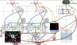
I do my layout in DIYLC first. It helps me bundle all advice and info I get and find in the layout. Attached is my current status of the layout. I would have loved to keep the input signals more to the bottom of the image, but that would have resulted in a ground loop. Choices....
If shielded wire is used, where would that be best? The (relatively) high-amperage filament supplies? The high-voltage B+?
Shielded wire is, as far as I know, for low level signals. It doesn't shield magnetic fields, which are caused by high currents. No help for heater wiring.
The magnetic field B ~ I/r.
* Limiting B can be done by keeping I low. So first source the output tubes and then the input tube. Lower heater current, so low B near the sensitive input.
* Limiting B can be done by keeping r large. Keep it away from sensitive circuits. As you have to supply the tube, come straight in and out (see Blencowe). Also crossing with 90 degrees angle implies a (n average) large distance
* Another possibility is to keep the feeding and returning currents closely together. That way both their B magnitudes are roughly equal, but because of the opposing current direction, they cancel.
* A further improvement is twisting. The minor distance differences between two parallel wires alternate averaging out even this small imbalance in B.
I do my layout in DIYLC first. It helps me bundle all advice and info I get and find in the layout. Attached is my current status of the layout. I would have loved to keep the input signals more to the bottom of the image, but that would have resulted in a ground loop. Choices....
Attachments
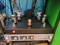
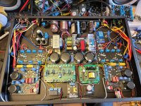
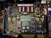
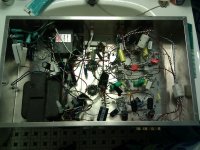
These are examples of somewhat messy, but hum free layout.
The first is a typical KT88 datasheet UL cathode biased amp making 60W.
The second is a 30W amp using some boards I created with the idea of them being universal. Notice the shielded signal cable from input to pot to input. If it weren't required, I'd skip it! This is the most important wiring in the amp.
Third is a picture of what not to do. This was one of my first attempts from about 10 years back.
Attachments
Last edited:
Really appreciate all the replies. Gotta love DIYAudio.com.
I started with DIYLC. It's a great tool, but for me, thinking something through and physically doing it are (unfortunately) the same thing. It amazes me that people have the patience to do the wiring in that program! Looks like you are doing a good job, Tom K.
Koda--Thanks for the pics. Those PCBs look quality. In the third pic, are those ferrules or magnets wrapped around the twisted wires?
Have decided to use the other side of the craft plywood to sketch out a center-odiented power supply to see how that feels.
Audiowize--Am noting your suggestion of how to detect induced voltage. My friend has an oscilloscope and once I've got the OTs and some wire down, would love to do that experiment.
Probably should have gotten a steel chassis, but was worried my tools (Dremel, 20V Ryobi cordless drill, good set of Bosch drill bits) may not be quite up to the task. But if this ever gets shipped, I plan on removing the heavy top-mounted elements when I do.
Again, really appreciate the comments. This has been great so far.
Take very good care with the position of your first choke in the clclc chain. It will radiate quite a strong magnetic field that only space, orientation or mu metal sheet will block. The smaller the first capacitor the stronger the field will be.
It need to be oriented 90 degres from your output transformer/interstage and tubes if sitting close to one of them. Idealy place it far from them and close to the power transformer at the opposite side. I like to place my choke under the power transformer at 90 degres but you need a deep chassis to do so. Some choke have good shielding and are less sensitive.
Magnetic field and electrical field are different and need different material to be isolated. Mu metal is very useful if you are space limited.
Any wire transporting 60hz or 120hz (50hz or 100hz) need to be twisted together or with a neutral and are those take care and keep away from small signal or high mu tubes. Signal and B+ are not really problematic and I prefer not to place them too neatly And like some chaos in their positionning.
Your heaters need to be balanced with either a center tap or a virtual one with two resistor.
Good grounding scheme is important and need to go from first PS capacitor to second PS capacitor to next capacitor to larger signal ground around output tube to smaller smaller signal ground around driver tube to rca input. The questions is often about where to connect the chassis ground and the IEC earth in all this. I have good success to put the chassis ground directly at the rca connection and the IEC earth at the end of the chassis, opposite side of it on a screw holding a transformer. In my opinion you should decide this final aspect by trying different way with a test speakers attached after the initial powering on and try different solution and choose the one that reduce the most the noise. With aluminium chassis it can be different than with a steel chassis. I test them with alligator jumper at the end and fix it where the noise is lower but when all other ground are well made this doesn't affect the end result much and I've never had to use floating eath or resistor or noise blocker on the IEC earth.
For a dht I stay away from AC on filament to avoid the distortion that come with it and now use small 20$ SMPS with a Faraday cage. It work so well and is very reliable and cheap and completely silent. For anything 6.3-7.5 volts I use the EPS-65-7.5-C from mean well with a 0.1 ohms resistor in serie with the + and - output of the smps. This replaced my rectifier cap regulator ccs etc and helped me getting my 808 tubes under 1mv ac of noise, not an easy task on a 7.5v 4A filament DHT tube. I know this is heresy for many but it work so well and I can't find any negative of using them.
My best recommendation is to look at many pictures of well made amplifiers on the web and check how they route the wires and where they generally place the components. I've put hours and hours finding way to make tube amplifiers dead silent since I use them on active horns speakers connected directly to the amplifiers. There is no place for noises in this use.
Last trick, avoid bad soldering joint and make sure the wire touch the other wire or tab before soldering, don't use the solder to make the connection but the components and wires themselves. Check your soldering quality by moving the wires. I avoid using the connection tab to do the connection but use them as support to the connection itself.
I've fixed a noisy amplifier of friends recently where a single cold solder joint on a capacitor negative leg was the problem. it was a pain to find this problem.
Last edited:
Really appreciate all the replies. Gotta love DIYAudio.com.
Koda--Thanks for the pics. Those PCBs look quality. In the third pic, are those ferrules or magnets wrapped around the twisted wires?
They were ferrite beads in an attempt to trap RF - That phono preamp could pick up FM radio!
Only the black PCB designs are mine 🙂
As far as your tools go, they shouldn't have a problem with steel - I used to think the same thing. I do use cobalt bits though. I also now punch holes for tubes instead of using a step drill - worth every cent I paid for the tool, too.
Here's a similar tool https://www.amazon.ca/LICHAMP-Manua...keywords=chassis+punch&qid=1614257784&sr=8-11
- Home
- Amplifiers
- Tubes / Valves
- Soliciting Comments on 1st Time Build Layout