Wow! Once again, thank you for the advice. You answered my questions in considerable detail, which I promise was very much appreciated.
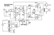
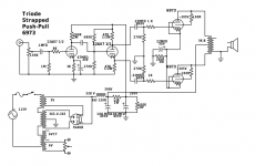
I've incorporated some of your suggestions, and made two separate schematics -- one triode strapped with no feedback (though I might insert some local feedback), and the other pentode with global negative feedback. The voltage drop from the choke loaded supply pretty much instantly solved my voltage problem. I've always just used a 100k or so resistor to ground at the end of the PSU for bleeding, is that not acceptably safe?
I'm a little confused by what you mean when you say, "Remove the 40uF cap, and use one more series Resistor with the 40uF cap to ground (choke, RC, RC, RC)." Is my configuration of choke, RC, bleeder not going to work? Do I need more RC filters, or is the current layout sufficient do you think?
I too mostly listen to CD's from my Oppo. I don't know it's actual RMS output, but it must be pretty high because I can blast music through my meager 5 Watt single ended KT88 amp. So, I think I might get just what I need from the triode strapped design, but I also wanted this to be a learning experience for both pentode and push-pull construction. To that end, I'll probably breadboard both iterations and see which one I like more.
Thanks again, sUMMER! You've been very helpful.

I prefer connecting from the choke output lead to the bleeder to ground. It does two things:
1. It puts a load directly on the choke, not on a 13k resistor (50k + 13k = 63k) which helps reduce the rise in high voltage during the power turn on before the tubes warm up.
2. If any of the other resistors in the power supply burn out, the bleeder will do its job when you turn off the power (at least for the first capacitor, and down the chain until it gets to the first burned out resistor). So, in any case, use resistors that will not burn out (even if the other circuitry shorts) let the primary fuse blow instead.
And yes, 50k is more of a load to the power supply, but it brings the voltage down quicker when the power is turned off than 100k at the end of the B+ series resistors string.
The 40uF cap has 33 Ohms of capacitive reactance at 120 Hz. If you use a 40uF cap before the choke, and load the B+ with 100mA, the ripple at the choke input will be 3.3V peak to peak. After that, the choke and next cap will reduce the ripple a lot.
If you use a choke input supply, the voltage from the rectifier to the choke is 365V * 1.414
= 516V peak to peak. The ripple will be reduced by the cap that follows the choke, but
now we are starting with 516V peak to peak to the choke, not the 3.3V peak to peak of the cap input supply version. If you have too much ripple (causing hum in the amp output), you will need to use another RC to get the ripple down (i.e in your case 200 Ohms and 40uF will reduce the ripple by about 6). You will know if you have too much ripple when you listen to the amp on your speakers, and at the distance that you listen to them.
The grid stopper of 8k Ohms for the 12AX7 is a little too large. The grid input capacitance including the miller capacitance could be about up to 150 pF (for a stage gain of 100). A 5k Ohm grid stopper would be about -1 dB at 20kHz. A 1k Ohm grid stopper is more appropriate than 8k.
And, depending on your circuit that feeds the input, you should use a much lower resistance volume control. Most CD players should be medium to low impedance out, and should be able to drive a 25k pot there. For a CD with low impedance out, the worst case
rotation position of a 25k pot is 12.5k driving the 12AX7 grid. If the 12AX7 gain is 1/2 of u (50), the miller capacitance will be less, about 75 pF (106k Ohms at 20 kHz). Now we are getting somewhere. We could use a 10k Ohm pot if the CD player can do it (or computer out, which probably drives 30 Ohm phones), and still be no more than -0.5dB at 20kHz for that part of your circuit, no matter where the volume control is turned. This will allow the rest of the amp circuity to have some high frequency roll off too.
In triode mode the 6973 control grids will load the 2nd half of the 12AX7 at high frequency. If it is too much and causes a high frequency roll off, a 12AU7 should solve that.
The output transformer will have a high frequency rolloff, but should be higher than 20kHz.
The 18k feedback resistor will have to be reduced in value, it is driving 100 Ohms in parallel with 1/GM of the 12AX7 (about 570 Ohms).
If you build both circuits, and you have a square wave generator, see what you get for (low frequency) slope on a 1 kHz square, and ringing on a 10 kHz square.
- Status
- This old topic is closed. If you want to reopen this topic, contact a moderator using the "Report Post" button.