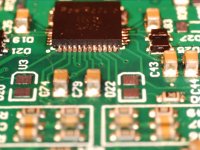
A little progress here the last day of the vacation. Now got the 2 chips soldered. Quit satisfied with the result.
Used a good deal of flux, then soldered dragging the iron over the pins, then used some solder wick to get rid of excess solder between the pins.
Will say it was not so easy, to really get the "legs" on the chip to show nice solder flow.
We'll all know when it is all assembled 😉
Used a good deal of flux, then soldered dragging the iron over the pins, then used some solder wick to get rid of excess solder between the pins.
Will say it was not so easy, to really get the "legs" on the chip to show nice solder flow.
We'll all know when it is all assembled 😉
Attachments
Ok today I tested the board ... and sadly it did not work.
I used a small power supply (old school transformer) with +-29V and additional regulated +-13V and 13V referenced to -29V for the gate driver.
but something is using power and the voltages dropped to ca. +25V, -23V, +-3V and 13V.
Firstly trying to solder this, I'll just have to admit that it is super difficult. And I have no real way of knowing whether it doesn't work down to a bad solder point somewhere, a short circuit (though I have tested almost all points before with an ohm meter, especially all the power pins), or the chips are fried by the oven or by handling ..... or I might have made a mistake in the design ..... ...
A learning is that with a board like this, you have to be able to separate the chips, so they can be tested one by one. This could be done with 0 ohm resistors in all the power pins .
Another thought is that I should have gotten the PCBs without any components but with a stensil. Then I could have used the stensil for the 2 amp chips, ensuring the right amount of solder paste before the oven. Using a toothpick to apply solder paste is just so inaccurate ...
Also as I have made big efforts in making cooling for the chip through the PCB, this just makes it a lot more difficult to do by hand, as you simply cant heat up the parts which is connected to larger copper fills on the board.
Have 6 more chips, and 4 more boards ...... not sure if I should try again ......
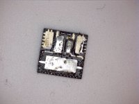
Almost same story for the other chip ....
Had hoped that desoldering one might have left the other one working .... but no such luck
And yes no wonder it didn't work 😉
One good thing though. After removing the 2 chips all the PSUs work as intended ..... but with no class d chips it doesn't really help 🙂
One learning could maybe be to pre-solder all pins and areas on the chip with some good solder and remove most before soldering to to the board.
Like with cables, wires and others it's always good to pre solder to get an easy solderable surface before joining
Attachments

Last edited: