Hello,
I have designed a board with the TAS3251. It is a HSSOP 56 pins package. The PCB and part of the assembly will be done at JLCPCB (Chine). I will solder the expensive components (TAS3251, output coils) and through holes.
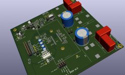
So the task will be to solder the chip in the middle of the board with little lateral clearance (see picture below), and no possibility to use a stencil by the PCB manufacturer. Sort of I put me in the corner. Have to choose between solder wire + flux approach, or solder paste + hot air (have both).
Any advice on the preferred technique to perform the task ?
Best regards,
JMF
I have designed a board with the TAS3251. It is a HSSOP 56 pins package. The PCB and part of the assembly will be done at JLCPCB (Chine). I will solder the expensive components (TAS3251, output coils) and through holes.
So the task will be to solder the chip in the middle of the board with little lateral clearance (see picture below), and no possibility to use a stencil by the PCB manufacturer. Sort of I put me in the corner. Have to choose between solder wire + flux approach, or solder paste + hot air (have both).
Any advice on the preferred technique to perform the task ?
Best regards,
JMF
Attachments
I would go for hot air as there are other components close to pads which will impede using a soldering iron along the pads.
I used to hand solder microprocessors to surface mount PCB's at 40 pins per inch.
I used solder paste applied with a syringe in a single line across the pads and a fine tip temperature controlled iron.
A good illuminated magnifier is more or less essential.
Tack the end pins first to get the chip aligned with the pads.
Close inspection is needed and a good liquid flux can help the solder flow if there are any bridges that need to be separated.
I agree that some of the decoupling caps look close to the pads. They could be hand soldered after the chip if needed.
Hot air definitely. Maybe try applying solder paste to the device legs rather than the PCB as a stencil can't be used? Use flux on the pcb to prevent the pads oxidizing.
I'd shield those electrolytics from the airflow with something. You may find the header pins plastic deforms a bit alas. Make sure to run the air just hot enough and be patient.
Unfortunately HSSOP is dense enough that stencil is normally needed to avoid bridging. I wonder if there's a way to make a 0.54mm pitch rake to clear solder paste between the pins? Perhaps try a sacrificial HSSOP chip?
I presume you wanted to ensure the expensive parts are not substituted with junk?
BTW hot air is really good because you can correct mistakes...
Last edited:
BTW hot air is really good because you can correct mistakes...
Hot air is good also because the IC will float into the centre once all solder melts.
Thanks for all your advices.
So option one would be solder paste applied with a syringe in a single line across the pads and hot air. This is on the top of the list.
I was also thinking about unsoldering the too near caps and resoldering them afterward.
Last option I had in mind, but I don't know if it makes sense was trying to do a mini stencil for just the HSSOP footprint with a laser cutter. But I haven't done any tests. Would some have experience about that ?
There are 2 reasons behind the TAS3251 not being soldered:
- JLCPCB does not offer that part in their part library (even extended),
- as it is a prototype and as there are 10 boards manufactured (to optimize costs), this will result in less money lost if the design has issues.
JMF
0.65mm is pretty fine to work reliably without clear soldermask between pins. You'd need the bare minimum of solder paste to improve the chances. 0.5mm which is even finer needs stencilling for reliable results without bridging time after time.
Definitely worth doing some practice with junk parts I think.
Definitely worth doing some practice with junk parts I think.
I've done a lot of prototyping of these fine pitch parts myself.
I have a JLC board coming on next week and have the same challenge you do.
I use 0.020 cHIPqUIK SILVER NEARING SOLDER
I have a JLC board coming on next week and have the same challenge you do.
I use 0.020 cHIPqUIK SILVER NEARING SOLDER
I too have a JLC board coming in next week with almost all parts assembled by them, except for some fine pitch ICs that they do not stock.
A pro assembler showed me the trick for getting these parts on the board reliably.
I use 0.020 inch ChipQuik silver bearing wire solder because it flows so nicely.
I tin one pin on the board, then get the IC lined up to the pads.
This way I can move the chip around and only have one melt point to deal with.
After I am happy with the alignment, I move to the other side of the IC and just slop solder on the pins until all of the pins and pads show visibly flowed solder.
I don't worry at all about solder covering multiple pins.
The I go back to the first side and repeat the process.
Next I use EasyQuik 0.062 desolder braid (purchased from Mouser) to very carefully remove the excess solder. If you position the braid so that you can still see the chip ends of the pins and hit the braid with the iron, then it's easy to see when the solder flows into the braid and the pins clear. The braid MUST be good quality with an effective flux in it. I like the EasyQuik stuff for this.
With a bit of practice, you can end up with just the right amount of solder left on the pins to give you good quality joints. And the good part is that you do not need to used those tiny pointed soldering iron tips that burn off their plating if you look at them sideways. A 1/16 tip works very nicely for this process. I've been doing this for many years, so it's easy for me, but it's a process that is not hard to pick up.
Last edited:
Thanks again for all your advices.
The TAS3251 pitch is 0.65mm. Better than 0.5 mm but still small.
I love the magic of Stencil / solder paste / hot air. But some of seems that I'm at the limit of syringe applied solder paste.
Adam advocates the solder wire way with extensive details. This Week-end, I ordered C1 and C2 soldering tips for drag soldering.
In all cases, needs pracicing a bit before jumping...
JMF
JMF11, in my experience the key to the use of paste is to use very little. I put a small amount of paste on a piece of cardboard with the syringe, then use a pointed Xacto blade to pick up just a little bit of the paste and apply it to the PCB pads. Then the part goes on and heat is applied.
You really don't have to worry too much about solder shorts unless you are really sloppy and generous in applying the paste. It's mostly flux. I have really good luck with this "stencil-less" technique. I would not want to do more than one or two boards this way though, it is rather painstaking.
One of my secrets is that the paste I use is Chipquik SMDLTLFP. It's a low-temperature paste and flows very well.
Ooh, that's the bismuth stuff, melting point 138C. I'd worry the part would fall off the board on a hot day 🙂
I use their SMD291SNL10 which is 96.5% Sn, 3% Ag, 0.5% Cu, which is almost eutectic, about 220C melting point.
I can see the advantage of the low temperature stuff if doing lots of plastic parts like LED displays and flatflex connectors - these are very easy to discolour if over temperature.
I use their SMD291SNL10 which is 96.5% Sn, 3% Ag, 0.5% Cu, which is almost eutectic, about 220C melting point.
I can see the advantage of the low temperature stuff if doing lots of plastic parts like LED displays and flatflex connectors - these are very easy to discolour if over temperature.
- Home
- Design & Build
- Construction Tips
- Soldering HSSOP in middle of a board paste or wire?