I live "off the grid" in Panama. It is actually very comfortable, but that is another story. One result of this is that I have a HUGE 48V battery bank (800aHr @ 48V) just sitting there asking to be used as a power supply for an amp. Now "48" is really 50-58VDC most of the time. Since most of my listening is at night, we are talking seriously CLEAN DC power. The only caveat is that it is single ended power, not balanced. I was thinking of building a Zen 9 power amp and Bride of Zen preamp, but then I saw the jfet-boz which looks interesting and the Tube Zen (which i started a different thread about - does it exist?)
The rest of my system is a home made speaker system modelled on the JBL Paragon using 14" JBLs with a JBL horn mid/hi driver (Quite efficient) with CD player or mp3 player for input (I know, but I just couldn't transport all my vinyl and turntable, etc. to Panama.)
I have made my own pcbs in the past, but they are rather amateurish so being able to use existing pcbs would really help ( or a design I can wire ptp).
What about it? Any one done this? Any thoughts or suggestions?
Thanks for the input.
forget tube zen - you'll get better sound if you build , say , PLH with doubled outputs , or ZV2 with BOZ (Bride of zen)
look at articles page at FW site
look at articles page at FW site
Last edited:
If you run balanced outputs, it's pretty easy to build a direct coupled
amplifier with a single clean DC rail by creating a ground between two power
resistors in series from V+ to V-. As this ground will only have to conduct low
currents (not output current) it will work fine and you can get as much as 100
watts or so of output into 8 ohms.
😎
amplifier with a single clean DC rail by creating a ground between two power
resistors in series from V+ to V-. As this ground will only have to conduct low
currents (not output current) it will work fine and you can get as much as 100
watts or so of output into 8 ohms.
😎
I have seen this done in low power situations (preamps, etc.) but did not think it could handle power amp applications.
look at psu solution in Quad 306 and 606 (caps and divider)
that way you can make any FW amp
take F5 for instance
when that's clear , grasp how to make F5X with same ; in that case , when load is gnd-free , you don't need Quad's solution for small signal gnd , simple resistance divider is enough ........ and everything is DC coupled , as long you're using small signal gnd for entire signal chain
That is interesting and I will definitely need to noodle through it at some point. For this project, however, I wanted to make a simple SE Class A amp like the Zen 9. The discussion of voltage dividers has me thinking about a different use for them. Since the jfet BoZ wants about 24V, SE, and I have about 50, could I run them from a divider? One would operate from +50 to +25 and the other from +25 to 0. Since the signal is NOT DC coupled, it shouldn't care and as long as each channel of the preamp is looking at 25VDC, it shouldn't care unless there would be some problem with the DC - ("ground") of one channel being attached to the DC+ of the other. I will try to work out a schematic of what I am talking about and post it, but it may have to be hand drawn. I know it seems off the wall, but the more I think about it, the more I think it might work. After all, nothing in the amp will have reference to EARTH ground. As long as I keep the signal "ground" separate from the power +/-, would it work?look at psu solution in Quad 306 and 606 (caps and divider)
when that's clear , grasp how to make F5X with same ; in that case , when load is gnd-free , you don't need Quad's solution for small signal gnd , simple resistance divider is enough ........ and everything is DC coupled , as long you're using small signal gnd for entire signal chain
it'll work , but ..... even if JFet Boz is tiny consumer , it's still better and cleaner solution to just shave positive rail , especially if you're going to use power gnd as gnd for your amp
Shaving the rail
What am I missing???
Thanks
OK, help me with the math here. This seems too simple. If the "sweet spot" is around 16V as NP said in another thread and it draws 5mA (another NP post) and I have 50V, 50V-16V=34V and 34V/5mA=6800R, so a 6.8k (?1/4W is fine?) resistor followed by a cap (?what size?) would drop my 50V to 16V for this preamp, correct? (would need to do one for each channel)it'll work , but ..... even if JFet Boz is tiny consumer , it's still better and cleaner solution to just shave positive rail , especially if you're going to use power gnd as gnd for your amp
What am I missing???
Thanks
P=U x I for resistor dissipation , then factor 3
however , it's better to make zenner follower series reg
with small NMos
if you need help for drawing it , say
however , it's better to make zenner follower series reg
with small NMos
if you need help for drawing it , say
OK, so the rest of the math is correct, but 34V x 5mA = .17W but x3 = .51 so use at least a 1W resistor, yes?P=U x I for resistor dissipation , then factor 3
I think I can draw one, but I'll post it for comments before building it.😉however , it's better to make zenner follower series reg
with small NMos
if you need help for drawing it , say
My thought was that I have such clean DC (battery) that I didn't want to add a potentially noisy zener. Am I being foolish?
FWIW, I have build innumerable kits, but I am pretty new at building from scratch and/or modifying designs for my needs.
Thanks for all the help.

you'll not have much noise , but certainly lower rail impedance , vs. RC solution
though - you can try both iterations , then choose
though - you can try both iterations , then choose
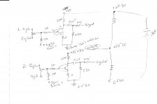
Again, excuse my crude hand drawing - hardly "eye candy"!if you need help for drawing it , say
A few questions:
- Should I have a largish (2200uF) cap in front of this, or not needed with battery?
- Are values OK? (20V Zener is one I have and I think the output is a bit lower than the zener rating, correct?)
- IRF610 for MOSFET OK? (I have some)
- What value range for cap at end?
- Is the regular diode necessary? Why? What does it do?
Attachments
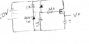
1. not needed
2. OK (Uout = Uz - Ugs)
3.ok
4. 470 - 1000uF ; you can also add bleeder resistor in parallel to cap ..... for 10-15mA
5. cap discharge path , in case when supply is off/disconnected
2. OK (Uout = Uz - Ugs)
3.ok
4. 470 - 1000uF ; you can also add bleeder resistor in parallel to cap ..... for 10-15mA
5. cap discharge path , in case when supply is off/disconnected
Thanks so much! I think I'll go with 1000uF and 2.2K @ 3W for bleeder (parts I have)
Now I get to play with the version of Eagle I just downloaded!! I know it is overkill for such a simple project, but I got to learn somehow. I'll post my results, but don't hold your breath.
Now I get to play with the version of Eagle I just downloaded!! I know it is overkill for such a simple project, but I got to learn somehow. I'll post my results, but don't hold your breath.
Could I use a 1k-1.5k resistor with an LED for bleeder? (serves two purposes.) Is 1/4W enough or higher?4. 470 - 1000uF ; you can also add bleeder resistor in parallel to cap ..... for 10-15mA
say 10mA for bleed through LED
LED will work at - roughly - 2V
so - 16V-2V is what you need across series resistor
as R=U/I , resistor is 14V/0.01A =1K4
use 2 x 2K7 in parallel
then current will be 14V/1K35=10.3mA
dissipation will be P=U x I = 14 x 0.0103=145mW
two common type small resistors of any kind (carbons 250mW , metal films 450-600mW for same size) will do the job
- Status
- Not open for further replies.
- Home
- Amplifiers
- Pass Labs
- "Solar" amp