For the last day or so, I've been messing around with Horbach Keele filters.
This absolutely blows my mind, but there does not appear to be any software available to simulate the directivity of an array.
I have a difficult time believing this; many of you have built arrays. How on earth is there no software to do this?
Here's a list of what I've looked at:
7) Akabak - it can simulate the directivity of an array, but only at a single frequency.
6) ABEC - can simulate the directivity of an array, but you'll spend the next two years of your life creating the model
5) Hornresp - can simulate the directivity of a single driver, not an array
4) VituixCad - I had really high hopes for this. As far as I can see, it can display the measurements that you make, but I don't see any way for it to simulate the performance of a driver based on it's diameter. IE, it can sim arrays as long as you actually build and measure the array first.
3) XDIR - it can simulate an array. It has no ability to include a crossover. I guess you could get 'in the ballpark' if you calculated the crossover phase shift manually.
2) FRD Consortium's VPR can do arrays, but can't do xovers
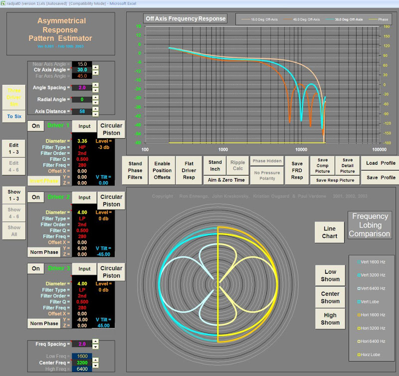
1) At the moment, the closing thing to a working array simulator is FRD Consortium's ARPE. But the website has been dead for years, and the software can't do bandpass filters properly. Which means I can't sim Horbach Keele filters.
Please tell me there's software that can do this. I don't want to write my own.
This absolutely blows my mind, but there does not appear to be any software available to simulate the directivity of an array.
I have a difficult time believing this; many of you have built arrays. How on earth is there no software to do this?
Here's a list of what I've looked at:
7) Akabak - it can simulate the directivity of an array, but only at a single frequency.
6) ABEC - can simulate the directivity of an array, but you'll spend the next two years of your life creating the model
5) Hornresp - can simulate the directivity of a single driver, not an array
4) VituixCad - I had really high hopes for this. As far as I can see, it can display the measurements that you make, but I don't see any way for it to simulate the performance of a driver based on it's diameter. IE, it can sim arrays as long as you actually build and measure the array first.
3) XDIR - it can simulate an array. It has no ability to include a crossover. I guess you could get 'in the ballpark' if you calculated the crossover phase shift manually.
2) FRD Consortium's VPR can do arrays, but can't do xovers
1) At the moment, the closing thing to a working array simulator is FRD Consortium's ARPE. But the website has been dead for years, and the software can't do bandpass filters properly. Which means I can't sim Horbach Keele filters.
Please tell me there's software that can do this. I don't want to write my own.
You know that xcel could effectively do that? 🙂
Not that setting it up would be exactly quick....
Not that setting it up would be exactly quick....
Microsoft Excel?
The ARPE spreadsheets seems to be the closest I can get to my goal. But it can't do proper bandpass filters.
Might be worthwhile to dig into the source code if it's not protected...
The ARPE spreadsheets seems to be the closest I can get to my goal. But it can't do proper bandpass filters.
Might be worthwhile to dig into the source code if it's not protected...
Use abec, really.
If you use the point source model in abec instead of bem it becomes much much more easy and it does what you need it to do.
One day you will have to bite the bullit; if you master abec you can throw all other sim software aside.
Cheers
If you use the point source model in abec instead of bem it becomes much much more easy and it does what you need it to do.
One day you will have to bite the bullit; if you master abec you can throw all other sim software aside.
Cheers
I believe BoxSim does what you want, but it is for Visaton drivers.
Currently I'm working on simulation software that can (if I understand) do that. I can give it to you, but it isn't finished yet (only passive filters, ...).
Currently I'm working on simulation software that can (if I understand) do that. I can give it to you, but it isn't finished yet (only passive filters, ...).
That depends heavily on what you are modelling. The actual simulation may take longer if you want accuracy up to high frequencies 😛6) ABEC - can simulate the directivity of an array, but you'll spend the next two years of your life creating the model
Are you talking direct drivers like the authors you mentioned, or do you want to array synergies or something? 😀
@ kessito
I have not used abec with point models yet. Then again, I used it to play around with horns/waveguides and explicitly desired models closer to a real build.
That depends heavily on what you are modelling. The actual simulation may take longer if you want accuracy up to high frequencies 😛
Are you talking direct drivers like the authors you mentioned, or do you want to array synergies or something? 😀
@ kessito
I have not used abec with point models yet. Then again, I used it to play around with horns/waveguides and explicitly desired models closer to a real build.
Something like ARPE. Where you can specify the diameter of a radiator and it's location, and ARPE will figure out the polar response.
ABEC can do this, but it's so freakin' dreadful to create all the elements.
Since I don't see any mention of an enclosure there I might be able to give you a slight head start or headache, who knows.
I dont ABEC supporst FIR filters, so I think you have to produce pre-filtered responses per driver and import those in abec...
The following code produces this with 5 different "drivers" with 4 pairs and one in the center. It follows the specs by the aforementioned authors of some 5-way design (though that one was vertical).

In the formula section you can change the diameter and distance of individual drivers.
Let me warn you though. For some reason my polar response is lopsided and I have no idea why.
Add as a direct sound script.
And as a bonus here is a bem solution without external CAD help. Solving this takes a while even at settings that won't allow useful resolution at higher frequencies.

by bem script
I dont ABEC supporst FIR filters, so I think you have to produce pre-filtered responses per driver and import those in abec...
The following code produces this with 5 different "drivers" with 4 pairs and one in the center. It follows the specs by the aforementioned authors of some 5-way design (though that one was vertical).
In the formula section you can change the diameter and distance of individual drivers.
Let me warn you though. For some reason my polar response is lopsided and I have no idea why.
Add as a direct sound script.
Code:
Subdomain_Properties
	Subdomain=1
	ElType=Exterior
	//IBPlane=z

formula
	bh = 20*2.54*0.01 //mm
	bw = 80*2.54*0.01 //mm
	bd = 30*0.01
	d1d = 1*2.54 //cm
	d2d = 2*2.54 //cm
	d2t = 1.5*2.54 //cm
	d3d = 4*2.54 //cm
	d3t = 4.5*2.54
	d4d = 8*2.54 //cm
	d4t = 12.5*2.54
	d5d = 15*2.54 //cm
	d5t = 31.25*2.54

Nodes "N"
	scale=1cm
	11 0 0 0
	21 { d2t} 0 0
	22 {-d2t} 0 0
	31 { d3t} 0 0
	32 {-d3t} 0 0
	41 { d4t} 0 0
	42 {-d4t} 0 0
	51 { d5t} 0 0
	52 {-d5t} 0 0

Pressure_Box "drv1"
	Subdomain=1
	DrvGroup=11
	DiaphShape=Disc
	dD=1 in

Pressure_Box "drv2r"
	Subdomain=1
	DrvGroup=21
	DiaphShape=Disc
	dD={d2d*0.01}
	RefNodes="N"
	Position=21
Pressure_Box "drv2l"
	Subdomain=1
	DrvGroup=22
	DiaphShape=Disc
	dD={d2d*0.01}
	RefNodes="N"
	Position=22

Pressure_Box "drv3r"
	Subdomain=1
	DrvGroup=31
	DiaphShape=Disc
	dD={d3d*0.01}
	RefNodes="N"
	Position=31
Pressure_Box "drv3l"
	Subdomain=1
	DrvGroup=32
	DiaphShape=Disc
	dD={d3d*0.01}
	RefNodes="N"
	Position=32

Pressure_Box "drv4r"
	Subdomain=1
	DrvGroup=41
	DiaphShape=Disc
	dD={d4d*0.01}
	RefNodes="N"
	Position=41
Pressure_Box "drv4l"
	Subdomain=1
	DrvGroup=42
	DiaphShape=Disc
	dD={d4d*0.01}
	RefNodes="N"
	Position=42

Pressure_Box "drv5r"
	Subdomain=1
	DrvGroup=51
	DiaphShape=Disc
	dD={d5d*0.01}
	RefNodes="N"
	Position=51
Pressure_Box "drv5l"
	Subdomain=1
	DrvGroup=52
	DiaphShape=Disc
	dD={d5d*0.01}
	RefNodes="N"
	Position=52
And as a bonus here is a bem solution without external CAD help. Solving this takes a while even at settings that won't allow useful resolution at higher frequencies.
by bem script
Code:
Control_Solver
	f1				=20Hz;
	f2				=10kHz;
	MeshFrequency	=10kHz;
	NumFrequencies	=50; Abscissa=log
	//Meshing=Delaunay
	//Meshing=BiFu
    Sym=y
    Dim=3D
	//NUC=false

Subdomain_Properties
	Subdomain=1
	ElType=Exterior
	//IBPlane=z

formula
	bh = 20*2.54*0.01 //mm
	bw = 80*2.54*0.01 //mm
	bd = 30*0.01
	d1d = 1*2.54 //cm
	d2d = 2*2.54 //cm
	d2t = 1.5*2.54 //cm
	d3d = 4*2.54 //cm
	d3t = 4.5*2.54
	d4d = 8*2.54 //cm
	d4t = 12.5*2.54
	d5d = 15*2.54 //cm
	d5t = 31.25*2.54

Nodes "N"
	1001 {-bw/2} {bh/2} 0
	1002 {-bw/2} {   0} 0
	1003 { bw/2} {   0} 0
	1004 { bw/2} {bh/2} 0
	1011 {-bw/2} {bh/2} {-bd}
	1012 {-bw/2} {   0} {-bd}
	1013 { bw/2} {   0} {-bd}
	1014 { bw/2} {bh/2} {-bd}

Elements "enclosure"
	Subdomain=1
	RefNodes="N"
	MeshFrequency=500Hz
	SwapNormals
	101 1001 1002 1012 1011
	102 1001 1011 1014 1004
	103 1003 1004 1014 1013
	104 1011 1012 1013 1014
	//105 1002 1003 1013 1012

Baffle "front"
	Subdomain=1
	Position=z
	MeshFrequency=2kHz
	hB = {bh}
	wB = {bw}
	11 Ref="d1" x=0 y=0
	21 Ref="d2r" x={ d2t*0.01} y=0
	22 Ref="d2l" x={-d2t*0.01} y=0
	31 Ref="d3r" x={ d3t*0.01} y=0
	32 Ref="d3l" x={-d3t*0.01} y=0
	41 Ref="d4r" x={ d4t*0.01} y=0
	42 Ref="d4l" x={-d4t*0.01} y=0
	51 Ref="d5r" x={ d5t*0.01} y=0
	52 Ref="d5l" x={-d5t*0.01} y=0

Diaphragm "d1"
	Subdomain=1
	DrvGroup=11
	dD={d1d*0.01}
	MeshFrequency=10kHz
	simple

Diaphragm "d2r"
	Subdomain=1
	DrvGroup=21
	dD={d2d*0.01}
	simple
Diaphragm "d2l"
	Subdomain=1
	DrvGroup=22
	dD={d2d*0.01}
	simple

Diaphragm "d3r"
	Subdomain=1
	DrvGroup=31
	dD={d3d*0.01}
	MeshFrequency=8kHz
	simple
Diaphragm "d3l"
	Subdomain=1
	DrvGroup=32
	dD={d3d*0.01}
	MeshFrequency=8kHz
	simple

Diaphragm "d4r"
	Subdomain=1
	DrvGroup=41
	dD={d4d*0.01}
	MeshFrequency=4kHz
	simple
Diaphragm "d4l"
	Subdomain=1
	DrvGroup=42
	dD={d4d*0.01}
	MeshFrequency=4kHz
	simple

Diaphragm "d5r"
	Subdomain=1
	DrvGroup=51
	dD={d5d*0.01}
	MeshFrequency=2kHz
	simple
Diaphragm "d5l"
	Subdomain=1
	DrvGroup=52
	dD={d5d*0.01}
	MeshFrequency=2kHz
	simple
Last edited:
Wow, that's very helpful. I tried to learn ABEC using a thread on a German forum. But trying to learn a difficult piece of software via a tutorial in German is an uphill battle.
My home computer is kind of a beast, I have sixteen Xeon cores so sim times aren't much of an issue (Waveguide model)
My home computer is kind of a beast, I have sixteen Xeon cores so sim times aren't much of an issue (Waveguide model)
Perhaps you were on diy-hifi-forum.eu?
I fought my own battles with this software today. Far too often I suffer from silent errors. Everything seems to be simulated, but the results are garbage, or almost nonexistant. It's really annoying to then stare at the scripts to see what could have gone wrong.
Interesting solution with that server. 😀 I'll get a taste of that with my next machine, as it might just be an 8 core ryzen 🙂
And since you may have missed my sneaky edit above. It is missing the crossover and I think you'll have to feed ABEC with pre-filtered responses for each driver to use FIR filters.
Another solution would be to do a ABEC direct sound simulation of the desired drivers at their distance and import the result in VituixCad for the actual crossover...
Problem would be that the former does not export the data in a form the latter understands. Luckily, it might be easy enough to write a script to convert the export into something importable, since its also relatively simple txt files.
Problem would be that the former does not export the data in a form the latter understands. Luckily, it might be easy enough to write a script to convert the export into something importable, since its also relatively simple txt files.
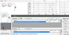
Simulated polar responses of single 1,2,4,8,15 inch drivers. Exported those as txt files from VacsViewer. Converted txt files using python into several that VituixCAD was happy to read. I have no idea if the phase response was correctly exported/imported.
In VituixCAD you can then use the response for a pair of distanced drivers. I tried to enter the active filters as seen in a table and graph here: http://www.linkwitzlab.com/Horbach-Keele Presentation Part 2 V4.pdf
Here is my result:

Some of the values are only eyeballed, but it looks quite similar I think. You might notice that I failed to implement the correct filter for the tweeter. If I could use the sum of 2 paths of active filters I could easily do it correctly, but I dont think I can and I dont see another solution.
Seems to do what it is supposed to, which might also indicate that the phase wasn't too bad? One probably shouldn't read too much into the rear response, as that wasn't even simulated anywhere. Unlike their vertical version, a horizontal 5-way would be a bit ridiculous due to its size. Then again it only looses directivity control at around 100 Hz, so one could probably easily scale it down to less absurd dimensions without much of a loss?
On the upper frequency end, control is worse than a speaker with a waveguide. But as the authors say a tweeter with its own control could be used. I wonder if a tweeter with a waveguide would fit well between the next pair of drivers?
Patrick, what are your ideas for this anyway?
I could imagine a synergy horn as small as can be and woofers for low end response at the sides for power and control.
I have attached my folder with the VituixCAD project (which should load with all settings resulting in the above), a python script (I used a jupyter notebook so no cmdline parameters), and the abec project (just a reduced version from the one before)
Hope it helps 🙂
In VituixCAD you can then use the response for a pair of distanced drivers. I tried to enter the active filters as seen in a table and graph here: http://www.linkwitzlab.com/Horbach-Keele Presentation Part 2 V4.pdf
Here is my result:
Some of the values are only eyeballed, but it looks quite similar I think. You might notice that I failed to implement the correct filter for the tweeter. If I could use the sum of 2 paths of active filters I could easily do it correctly, but I dont think I can and I dont see another solution.
Seems to do what it is supposed to, which might also indicate that the phase wasn't too bad? One probably shouldn't read too much into the rear response, as that wasn't even simulated anywhere. Unlike their vertical version, a horizontal 5-way would be a bit ridiculous due to its size. Then again it only looses directivity control at around 100 Hz, so one could probably easily scale it down to less absurd dimensions without much of a loss?
On the upper frequency end, control is worse than a speaker with a waveguide. But as the authors say a tweeter with its own control could be used. I wonder if a tweeter with a waveguide would fit well between the next pair of drivers?
Patrick, what are your ideas for this anyway?
I could imagine a synergy horn as small as can be and woofers for low end response at the sides for power and control.
I have attached my folder with the VituixCAD project (which should load with all settings resulting in the above), a python script (I used a jupyter notebook so no cmdline parameters), and the abec project (just a reduced version from the one before)
Hope it helps 🙂
Attachments
^You should remove excess phase from the measurements. Adjust timing of measurements (below frequency responses in Drivers tab) to negative value giving close to minimum phase responses.
Another option is to use Calculator tool. You can convert all responses to Minimum phase or set constant negative time offset before loading to main program.
Another option is to use Calculator tool. You can convert all responses to Minimum phase or set constant negative time offset before loading to main program.
4) VituixCad - I had really high hopes for this. As far as I can see, it can display the measurements that you make, but I don't see any way for it to simulate the performance of a driver based on it's diameter. IE, it can sim arrays as long as you actually build and measure the array first.
This is answered with video lessons in VituixCAD thread. Several options for directivity estimation is available, though radiator is calculated as ideal piston only. Calculator tool enables for example mixing with flat response if BesselJ1 function is too strong.
Oh now that looks a lot better and now it might be easier to dial in the other parameters better.^You should remove excess phase from the measurements. Adjust timing of measurements (below frequency responses in Drivers tab) to negative value giving close to minimum phase responses.

Thank you very much. Also for the software 🙂
Since you appear to be reading this. Is it possible to construct the red filter in VituixCAD? The right part, where its just a sudden constant 0dB is what I fail to reproduce. With the sum of 2 active filter paths I see how I could do it.

If you use "Edge" and place the "mic" in a number of strategi locations, you will be able to get directivity information.
Tolvan Data
Oops - the was a dedicated app for this, XDIR:
Tolvan Data
//
Tolvan Data
Oops - the was a dedicated app for this, XDIR:
Tolvan Data
//
Is it possible to construct the red filter in VituixCAD?
Yes with Calculator tool and Transfer function block, but x/o frequency can't be adjusted without creating new filter response.
Create low pass filter section with H-K MTM and brickwall blocks. Export Filter gain of driver to text file. Load exported response to B response in Calculator tool. Load flat 0dB response to A list. Select Subtract A-B, select destination directory and save the result with Calculate&Save button. Add Transfer function block for high pass and load calculation result. Not so nice but works for occasional testing.
Looks like this
Attachments
Ah I see. I dont think I understood you correctly. I just constructed the high- and lowpass section for the tweeter individually with brickwall filters for both, exported them, loaded them as A and B, summed with A+B.
This leaves a beauty mark though, as the resultant filter shows some interpolation between the brickwalls leaving a short slope. Your example has it, too.
While this solution perhaps has too many steps (ideally speaking), the ability to bypass crossover blocks and the fact that the main and calculator windows are independend of each other, let this solution remain pretty fast actually 🙂
Unfortunately linkwitzlab appears to be down, so I cant see the paper to try to hone in on the given parameters. Oh well.
Thank you very much 🙂
^VituixCAD has 1/48 oct steps in frequency axis. Perfect brickwall is not possible to show (and convert from frequency to time domain).
I have both AES papers (Part I & II) of Horbach & Keele. Authors wrote below small graph you attached:
Text does not point out that FIR needs much more taps for accurate IR if there is brickwall at fNx3. Therefore this filter is implemented in VituixCAD with proposed straight ramp from fNx3 to fNx6. Adjustable R parameter would be possible to add but I think that won't make it better.
I have both AES papers (Part I & II) of Horbach & Keele. Authors wrote below small graph you attached:
The dashed lines represent one possible extension of the responses that serves to smooth the sudden transition that occurs at this frequency to simplify filter implementation.
Text does not point out that FIR needs much more taps for accurate IR if there is brickwall at fNx3. Therefore this filter is implemented in VituixCAD with proposed straight ramp from fNx3 to fNx6. Adjustable R parameter would be possible to add but I think that won't make it better.
- Status
- Not open for further replies.
- Home
- Design & Build
- Software Tools
- Software to Predict Directivity