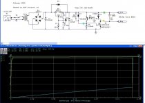
I've built a softstart circuit based on Rob Elliot's Project 39 (Figure 2). It doesn't work, althogh the simulation of it appears that it should. I'm not that experienced, and I already picked up and fixed an error on my pcb, but I can't find any others, so here is the circuit and simulation reslults-- do I have this right?
What happens is the "delay" output provides 12V immediately, without any delay. Both LEDs illuminate immediately as well. According to my calcs and the sim, the circuit should provide about a 6 second delay, keeping the relay "ground" at 12V until the 6 seconds hits, at which point the relay "ground" contact will go to about zero and the relay will then actuate.
(I actually used the BC558 and MTP3055 specified in the project, but simulated the other devices shown)
Comments appreciated.
Attachments
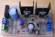
Here is the pcb layout
Layout Image
Ahhh.....yeah .... I already picked up the fact that the plus and minus terminals of the input filter caps were both grounded, and cut the trace where indicated (you can actually see this on the top view picture above). I've got multiple outputs, 2 for the relays (right side) and 2 for the undelayed DC (top (not implemented on the physical board) and bottom left). This is a one sided board with a bottom layer (in blue) and 2 jumpers in red.
Anyway the power supply part works fine, its the delay part that's giving me trouble. Perhaps C8 (22 uF on layout but 100uF as implemented) is shorted to the positive rail, bypassing R6 (which is actually the combination of two series R's on the board...one which is adjustable) but I cannot see how this is so....
Also, R1 on the schematic is the blue adjustable resistor on the board, set for the value indicated in order to provide 12V.
It looks like the MTP3055 drain and source are reversed. The center pin of the MTP3055 is the drain and should connect to the relay. It appears that the center pin is going to ground.
Good Luck!
GregoryD
Good Luck!
GregoryD
??
Though I have looked at the MTP3055 data sheet hundreds of times, (here), (ok, not really, maybe about 30) you may have something there! Boy I hope you are correct! I'll try that out and get back to everyone. Thanks for the help, I know it can't be easy to look at someone's design over 3 docs like you have done.
It looks like the MTP3055 drain and source are reversed. The center pin of the MTP3055 is the drain and should connect to the relay. It appears that the center pin is going to ground.
Though I have looked at the MTP3055 data sheet hundreds of times, (here), (ok, not really, maybe about 30) you may have something there! Boy I hope you are correct! I'll try that out and get back to everyone. Thanks for the help, I know it can't be easy to look at someone's design over 3 docs like you have done.
It Works!
OK, i've swapped the FET pins and its now working. Apparently, as suggested by GregoryD, my layout has the drain and source pins in each others spots. Whoops.
More details on the layout that are not shown in the schematic-
R6 is a 100K fixed resistor in series with a 500K multiturn cermet potentiometer. This gives me the ability to alter the delay from about 2 seconds to about 11 seconds by turning it counterclockwise (more ccw = longer delay).
R1 is also a multiturn trimpot, allowing me to set the output voltage at any DC value, turning this clockwise increases the DC voltage.
So this board can take AC, turn it into any value of DC and delay that DC up to about 11 seconds in its current implementation, though I'm sure I could go longer or shorter by changing capacitor and resistor values. Pretty neat.
Thanks GregoryD for your help, you really saved me a lot of time.
- Status
- Not open for further replies.
- Home
- Amplifiers
- Solid State
- SoftStart Not Working... Help!