I have a bunch of relays here and trying to figure out the best way to set this up on ESPs website he states that using a SSR as part of the circuit prevents the need from using a triac and octocoupler. I am using SL32s in series (values were given to antherm to figured out instead of resistors and thinking of using an omron ly2 SSR as the main relay. The circuit will eventually get more and more advanced as it is to triamp powered speakers but for now I have an under rated 800va toroid capable of 1kva for about 2hrs before heat is an issue. I found a low voltage control system that would be able to activate all the amps at the same time which would be nice and convieant but want to concentrate on a soft start / inrush limiter for now. The LY2 looks like it also has a step down transformer integrated to 24vac which is nice also. In addition to a fused iec power inlet I am also using a push button circuit breaker. I would like the sl32s to limit the inrush and provide a softstart and then have them get cut from the circuit once the amp is powered on rod Elliot seems to make this sound easy with the components I have rather then adding the triac and octocoupler and possibly some diodes by simply just hooking it up. Down the road heat, DC speaker protection and of course a 12v trigger will be added so the 3 amps and speakers are all well protected and I would like the relays to cut off the juice off at the at the mains/primaries so that everything is nice and safe with no chances of blowing anything up. So long story short, is this set up all I need to bypass the thermistors once the relay is activated? What is the best load to test it with prior to putting the primaries on my power supply and risk blowing out a bunch of stuff or damaging my toroid?
Hi,
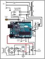
I think your are the right person and the right project to try my power on/off sequence technique. The only thing that you need it is to know how to program the Arduino Uno micro. Right now I am using the Zbasic micro to ramp the AC UP/DOWN on power ON/OFF in my 3 amplifiers. By slowly ramp the AC it will eliminate the inrush current and also will allow to slowly charge the capacitors. If you are interesting I will provide you the software so you can try it. The software it is in beta test because I converter it from ZBASIC to Arduino software format. Attached it is a drawing showing what you need and how to wiring it. It is a simple circuit. Everything it is done in the programming. Right now it is running in the Arduino board with no problems. I have the technique running for 2 years in 3 of my amplifiers with not problems. Let me know if you are interesting.
I think your are the right person and the right project to try my power on/off sequence technique. The only thing that you need it is to know how to program the Arduino Uno micro. Right now I am using the Zbasic micro to ramp the AC UP/DOWN on power ON/OFF in my 3 amplifiers. By slowly ramp the AC it will eliminate the inrush current and also will allow to slowly charge the capacitors. If you are interesting I will provide you the software so you can try it. The software it is in beta test because I converter it from ZBASIC to Arduino software format. Attached it is a drawing showing what you need and how to wiring it. It is a simple circuit. Everything it is done in the programming. Right now it is running in the Arduino board with no problems. I have the technique running for 2 years in 3 of my amplifiers with not problems. Let me know if you are interesting.
actually i use a lot of adruinos and raspberrys for prototyping things for the rest of the product line - its basically HA, AVD, green solutions, etc all in one. I heard the Audrinos aren't great for running nonstop? is that accurate?
I will most certainly use your design and perhaps together we can add to it but can you or someone else assist with my original question about using a SSR to bypass the need of triacs and octocouplers? I will send you my email addy via PM for the audrinos sketch. If it is a solid solution i would certainly purchase the chips and pins, etc to make the audrino solid for long term use without going down.
I will most certainly use your design and perhaps together we can add to it but can you or someone else assist with my original question about using a SSR to bypass the need of triacs and octocouplers? I will send you my email addy via PM for the audrinos sketch. If it is a solid solution i would certainly purchase the chips and pins, etc to make the audrino solid for long term use without going down.
Hi,
That it is great that you are willing to try my design. To do the AC ramp I used an SSR or a home made triac SSR using the MOC3020 triac driver. What I want to demonstrate it is how easy it is using a micro and the triac to prevent the current inrush when power ON the amplifier. Also I sync the ramp using the zero crossing to reduces or minimizes the inrush current.
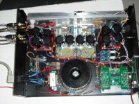
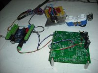
Attached it is 2 pictures showing the prototype that consist of the micro Arduino UNO , the home made SSR using the MOC3020 with a triac BTA25600. The green board it is the control board that I used to control all the functions of my amplifier. The prototype it is running with no problems.
Attachments
Missing link ? 😀Hi,
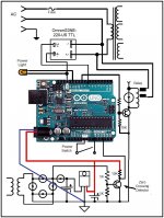
Attached it is the drawing. Do not what happened to it after I loaded it. Okay I found the problem it is was to large.
Attachments
- Status
- Not open for further replies.
- Home
- Amplifiers
- Power Supplies
- Soft start w inrush limiting and bypassing


