Hello,
Please, check this soft start schematic and if you see any hidden problems can write here ...
Until CAPs are loading .... the current is going thru resistor .... when it is used by the amp ... the current is going from the rectifier bridge + from caps ( by reverse diode .... )
No relays ... no time control .... but maybe another problems ???
I need approvals for that kind of wiring ..
Regards
Attachments
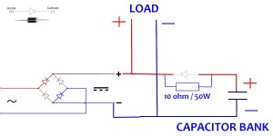
Not a bad attempt of avoiding the relay. As I see it, you have another unfortunate ripple effect:
You will always have a charging ripple, going to the load, that is increased with at least the forward voltage of the diode.
In order to charge the capacitor bank, the (diode) anode voltage needs to be lower than the (diode) cathode voltage. By how much depends on the charging current to the C-bank. In order to get energy to the load from the capacitor bank during low source voltage periods), the diode needs to be forward biased. Thus, the voltage to the load jumps from a reverse diode bias (depending on the charging current) and down to a forward voltage bias of the diode.
How I see it. Good to see you are experimenting with traditional solutions.
Last edited:
Another issue is that the capacitor can only be recharged through the 10 Ohm resistor which by itself can introduce significant supply voltage sag if the amp demands a lot of current.
Regards,
Oleg
Regards,
Oleg
Don't do it, use a NTC thermistor bypassed by a relay, in that way if the relay fails there is still no problem
Soft starts are normally needed to prevent high inrush currents caused by the transformer primary winding appearing as a very low impedance at switch on.
What is connected to the secondary doesn't play such a large part. Even with the secondary not connected to anything, the inrush is still massive.
Your circuit also has the problem of a low recharge rate for the cap should a large current be drawn. That means the DC supply to the amp will fall and not recover quickly.
Is it possible to use SCR instead of diode to short the resistor ... ? any schematic or web link ? ( dc relay are so expensive .. ) ....
Hi,
I already have a softstart on transformer primary --> resistor + relay ...
But capacitor bank is about 2 x 100 000 uF ... and I don't know what's will happen to the caps if they don't have current limiting resisitor too ??? Is it bad for caps ??
I already have a softstart on transformer primary --> resistor + relay ...
But capacitor bank is about 2 x 100 000 uF ... and I don't know what's will happen to the caps if they don't have current limiting resisitor too ??? Is it bad for caps ??
Its not bad for the caps but it probably is 'bad' for the transformer which will be attempting to deliver massive short duration charging pulses on each half cycle. That could easily push the transformer into saturation under those conditions causing it to run hotter than it should. There are other problems as well.
I can not understand the logic behind those wanting to use massive oversized capacitor banks in the belief its some generally good thing.
I can not understand the logic behind those wanting to use massive oversized capacitor banks in the belief its some generally good thing.
THANK YOU !
May I ask why when the primary is initially powered thru resistor .... why the caps that on that moment are short circuit the secondary will not suffer overcurrent ??
Regards,
Emil
May I ask why when the primary is initially powered thru resistor .... why the caps that on that moment are short circuit the secondary will not suffer overcurrent ??
Regards,
Emil
Your soft start on the primary will limit initial current... by how much we don't know... however the transformer will suffer no damage for short duration overloads (durations of many seconds to minutes).
The caps have no maximum current inrush limitation, they will draw as much as the transformer and rectifier can deliver. What will happen is that the current is so large that other circuit impedances and resistances (wiring, fuses, plugs and sockets) come into play which automatically tend to limit the maximum peak current drawn.
When your soft start period is over and full mains is applied to the transformer is when the long term problems of excess capacitance can come into play. If you draw for example 3 amps from a rail then it doesn't matter whether you have 1000uF or 100,000uF of capacitance, the power dissipated in the load is the same (disregarding small differences due to different ripple voltages). What does matter is that this amount of power or energy has to be put back into the capacitors and the smaller cap draws less current over a longer period of time compared to the oversized caps which only draw a short pulse of current for a much small time period.
Remember the bridge rectifier and transformer only supply current when the AC part of the waveform exceeds the voltage on the cap. For all the rest of the AC cycle no current flows. The small cap has seen its voltage fall more under load and so the transformer conducts for longer (and at lower current) to back the charge.
That peaky high current pulse can push the transformer into saturation causing it to run hotter over time, it also draws high current peaks through the rectifiers (which need to be able to withstand that) and also increases the possibility of radiated interference from the wiring carrying these high currents.
Mooly, I have always assumed a transformer first order to be described by a coil between the transformer inputs (the inductance of the primary winding on the core) followed by an ideal transformer to the output. Then it seems that a resistance inserted in the primary winding will translate to the secondary (with the square of Ns/Np I guess) such that it also protects the bank capacitors and the transformer from very high surge currents. Am I wrong here?
Put the soft start on the ac primary side of the transformer
I came up with a triac based soft start circuit controlled by an 8 pin PIC.
The PIC monitors the mains and on power up slowly increases the phase angle until it passes full mains.
If the mains fails it starts again.
My circuit will work with up to 2000 watts load.
Sorry cant provide a circuit diagram as my website host has given up on me.
Objection, your Honor!
Current beats of that nature will heat the windings due to the current surges but as long as they are symmetrical, not force the magnetic flux to one side and cause the core to drift into saturation. Am I wrong (again)?
Disregarding the capacitance of the bank, the same charge (energy) is taken out of the bank for the load between two rectified peaks. With a small capacitance, the voltage on the capacitor bank will reduce more and the transformer has to recharge from a lower bank voltage. With a high-capacitance bank, the voltage reduces less but the capacitance is higher for the re-fill.
In both cases, it is about the same amount of charge (energy) that has to be re-filled by the transformer. Wrong once more?
I rest my case, your Honor
Last edited:
Mooly, I have always assumed a transformer first order to be described by a coil between the transformer inputs (the inductance of the primary winding on the core) followed by an ideal transformer to the output. Then it seems that a resistance inserted in the primary winding will translate to the secondary (with the square of Ns/Np I guess) such that it also protects the bank capacitors and the transformer from very high surge currents. Am I wrong here?
Of course initial limiting of the primary current will also limit the maximum secondary current available, but that isn't the problem. The caps have no worry with a high initial charge current, neither does the transformer in supplying it. They don't need protecting against anything at switch on.
It is when the soft start has done its thing and is effectively shorted out that possible long term problems begin.
Soft starts have (imo) become fashionable when in practice they probably aren't needed for the majority of projects.
- Status
- Not open for further replies.
- Home
- Amplifiers
- Power Supplies
- soft start question ... no relay ...